Robotic catheter system

a robotic catheter and catheter technology, applied in the field of robotic catheter systems, can solve problems such as death and variety of ailments

Active Publication Date: 2015-10-20
ST JUDE MEDICAL ATRIAL FIBRILLATION DIV
View PDF197 Cites 38 Cited by
  • Summary
  • Abstract
  • Description
  • Claims
  • Application Information

AI Technical Summary

Problems solved by technology

Arrhythmia can create a variety of dangerous conditions including irregular heart rates, loss of synchronous atrioventricular contractions and stasis of blood flow which can lead to a variety of ailments and even death.

Method used


Image

  • Robotic catheter system
  • Robotic catheter system
  • Robotic catheter system

Examples


first embodiment

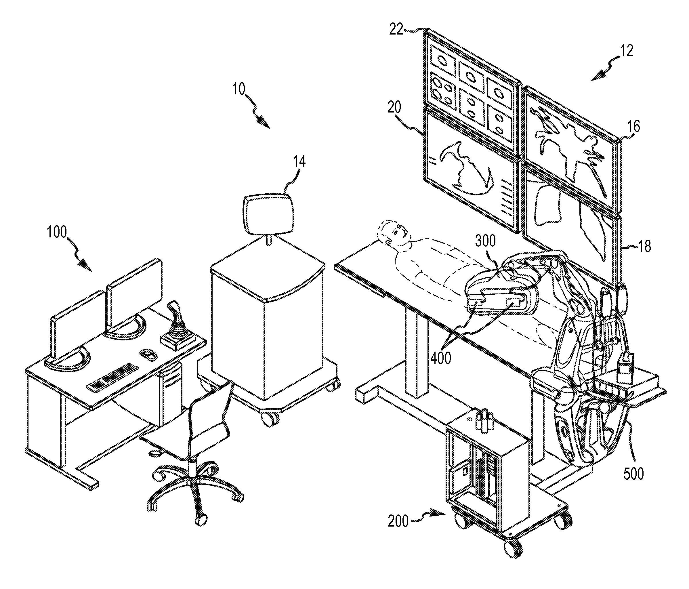
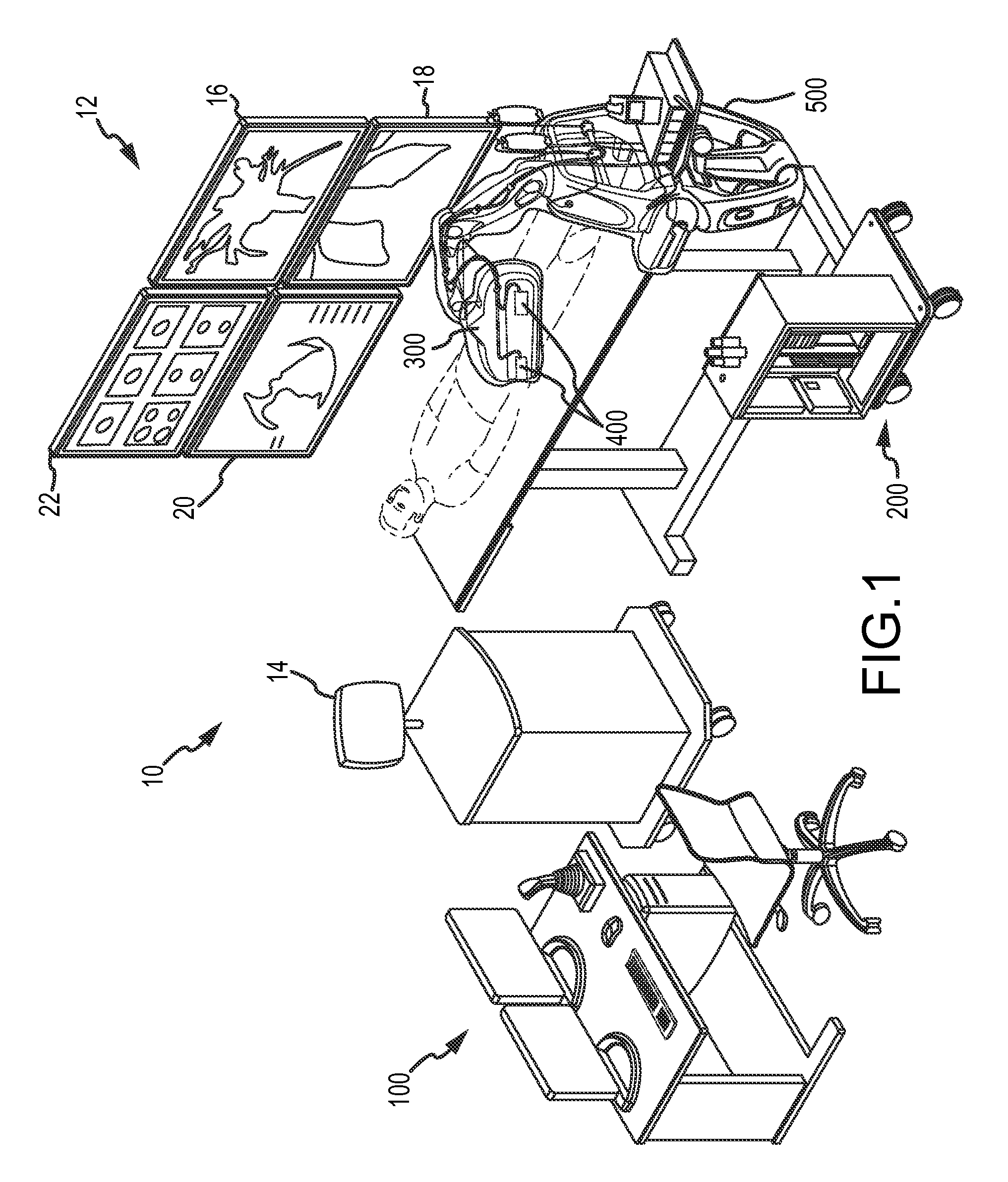
[0069]As generally shown in FIGS. 1 and 3a-5e and discussed in greater detail below, manipulator assembly 302 may respectively include both catheter and sheath manipulator mechanisms 304, 306. In this arrangement, the catheter and sheath manipulator mechanisms 304, 306 may be aligned such that the catheter can pass through the sheath in a coaxial arrangement. Each mechanism 304, 306 may be further capable of independent advancement / retraction (shown generally as directions D1 and D2) and independent four-wire steering control (e.g., eight total steering wires, comprising four sheath control wires and four catheter control wires), as discussed in detail below. It should also be understood that, while both the catheter and sheath may be capable of independent control, in alternative embodiments the system may only provide for control of one device while allowing the other device to remain passive (e.g., the sheath is actively controlled while the catheter is passive or “along for the ...

second embodiment

[0092]Referring to FIGS. 7a and 7b, isometric diagrammatic views of a manipulator support structure 550 are illustrated. Manipulator support structure 550 may generally include a support frame 552 including retractable wheels 554 and attachment assembly 556 for attachment to operation bed 518. A plurality of support linkages 558 may be provided for accurately positioning robotic catheter manipulator assembly 300. As shown in FIG. 7a, a handle 560 may be provided for assisting a user with extending attachment assembly 556 to an opposite side of bed 518. As shown in FIGS. 7a and 7b, in use, manipulator support structure 550 may be wheeled to operation bed 518 and attached thereto by attachment assembly 556. Thereafter, wheels 554 may be pivoted upwards upon release by a step-pedal system 562 to be positioned out of the path of operating personnel.

third embodiment

[0093]Referring to FIGS. 8a-8c, isometric and related diagrammatic views of a manipulator support structure 600, and various components thereof are illustrated. Manipulator support structure 600 may generally include a portable unit 602 for transportation of manipulator support structure 600 and its related components. Structure 600 may include attachment assembly 604 for attachment to operation bed 518, and a plurality of support linkages 606 for accurately positioning robotic catheter manipulator assembly 300. Referring to FIGS. 8a and 8b, in use, manipulator support structure 600 may be wheeled to operation bed 518 and attached thereto by attachment assembly 604, and thereafter detached and placed in portable unit 602 for transportation.


PUM


Abstract

A robotic system for manipulating a catheter with a plurality of steering wires longitudinally situated within a length of the catheter includes a user interface configured to display a view of an anatomical model and to receive one or more user inputs; a catheter manipulator assembly configured to linearly actuate one or more control members of a catheter; and a robotic controller configured to provide a view of an anatomical model to the user interface; accept one or more user inputs from the user interface; register the one or more user inputs to a coordinate system associated with the anatomical model; compute one or more actuator commands from the one or more registered inputs; and cause the catheter manipulator assembly to linearly actuate one or more control members of a catheter in accordance with the computed actuator commands.

Description

CROSS REFERENCE TO RELATED APPLICATIONS[0001]This application relates to and is a continuation-in-part of and claims the benefit of and priority to U.S. patent application Ser. No. 12 / 347,811 filed 31 Dec. 2008 (the '811 application), now U.S. Pat. No. 8,343,096 which in turn claims the benefit of and priority to U.S. provisional patent application Nos. 61 / 040,143 filed 27 Mar. 2008 (the '143 application) and 61 / 099,904 filed 24 Sep. 2008 (the '904 application), the entire disclosure of each of the '811 application, the '143 application, and the '904 application are hereby incorporated by reference as though fully set forth herein.BACKGROUND OF THE INVENTION[0002]a. Field of the Invention[0003]This invention relates to a robotic catheter system and method for automated control of a catheter and related components. In particular, the instant invention relates to a robotic catheter system for manipulating a catheter and related components, for example, for diagnostic, therapeutic, map...

Claims


Application Information

Patent Timeline
Patent Type & Authority Patents(United States)
IPC IPC(8): A61B19/00A61B17/00A61M25/01
CPCA61B19/2203A61B19/5244A61B19/56A61B2017/00026A61B2017/00477A61B2019/2211A61B2019/2223A61B2019/2234A61B2019/2242A61B2019/2273A61B2019/2276A61B2019/2292A61B2019/2296A61B2019/464A61B2019/507A61B2019/5229A61M25/0147A61B2034/742A61B2090/064A61B34/71A61B2034/301A61B34/25A61B34/30A61B34/37A61B2034/305A61B2034/741A61B34/76A61B34/77A61B2034/107A61B2090/372A61B2034/303A61B34/20A61M2205/33A61M2205/505A61M2210/125
Inventor OLSON, ERIC S.HAUCK, JOHN A.PATRONIK, NICHOLAS A.KIRSCHENMAN, MARK B.SHAQUER, CEMGANJI, YUSOF
Owner ST JUDE MEDICAL ATRIAL FIBRILLATION DIV
Why Eureka
Try Eureka