Device for blocking a vehicle, method therefor and loading-unloading station provided therewith

a technology for blocking vehicles and vehicles, applied in the direction of braking systems, transportation items, transportation vehicles, etc., can solve the problems of large variation in vehicles, blockage devices are relatively complex, and blocking devices do not operate optimally for all vehicles, so as to increase the utility of such a station

Active Publication Date: 2015-10-20
STERTIL
View PDF14 Cites 16 Cited by
  • Summary
  • Abstract
  • Description
  • Claims
  • Application Information

AI Technical Summary

Benefits of technology

[0018]By providing height-adjusting means the blocking means can engage at a desired height on the wheel of the vehicle. The height-adjusting means are adapted here to the vehicle for blocking. This can be performed manually by a driver and / or a location manager, for instance an employee of the distribution center, as well as automatically. The engaging height of the blocking means on the wheel of the vehicle for blocking is hereby adapted to the type of vehicle. This increases the possible uses of the device according to the invention. It is also possible to adapt the actual engaging height of the blocking means to the blocking requirement, for instance a relatively low engaging height in order to prevent the vehicle rolling away during loading and / or unloading, and for instance a relatively high engaging height in order to prevent unauthorized driving away with the vehicle during parking of the vehicle. This enhances the applicability and the possible uses of the device according to the invention.
[0038]Such a loading-unloading station provides the same effects and advantages as described in respect of the device. In addition, the use of the height-adjusting means makes it possible to use each individual station for all categories and types of vehicle. This further increases the utility of such a station.

Problems solved by technology

Such blocking devices are relatively complex due to the number of parts required, and particularly the drives required.
A problem occurring in practice with blocking devices is the great variation in vehicles which can occur.
The blocking device does not therefore operate optimally for all vehicles, whereby locations provided with a blocking device, such as at a distribution centre, cannot be employed with full flexibility for all types of vehicle.

Method used


Image

  • Device for blocking a vehicle, method therefor and loading-unloading station provided therewith
  • Device for blocking a vehicle, method therefor and loading-unloading station provided therewith
  • Device for blocking a vehicle, method therefor and loading-unloading station provided therewith

Examples


Embodiment Construction

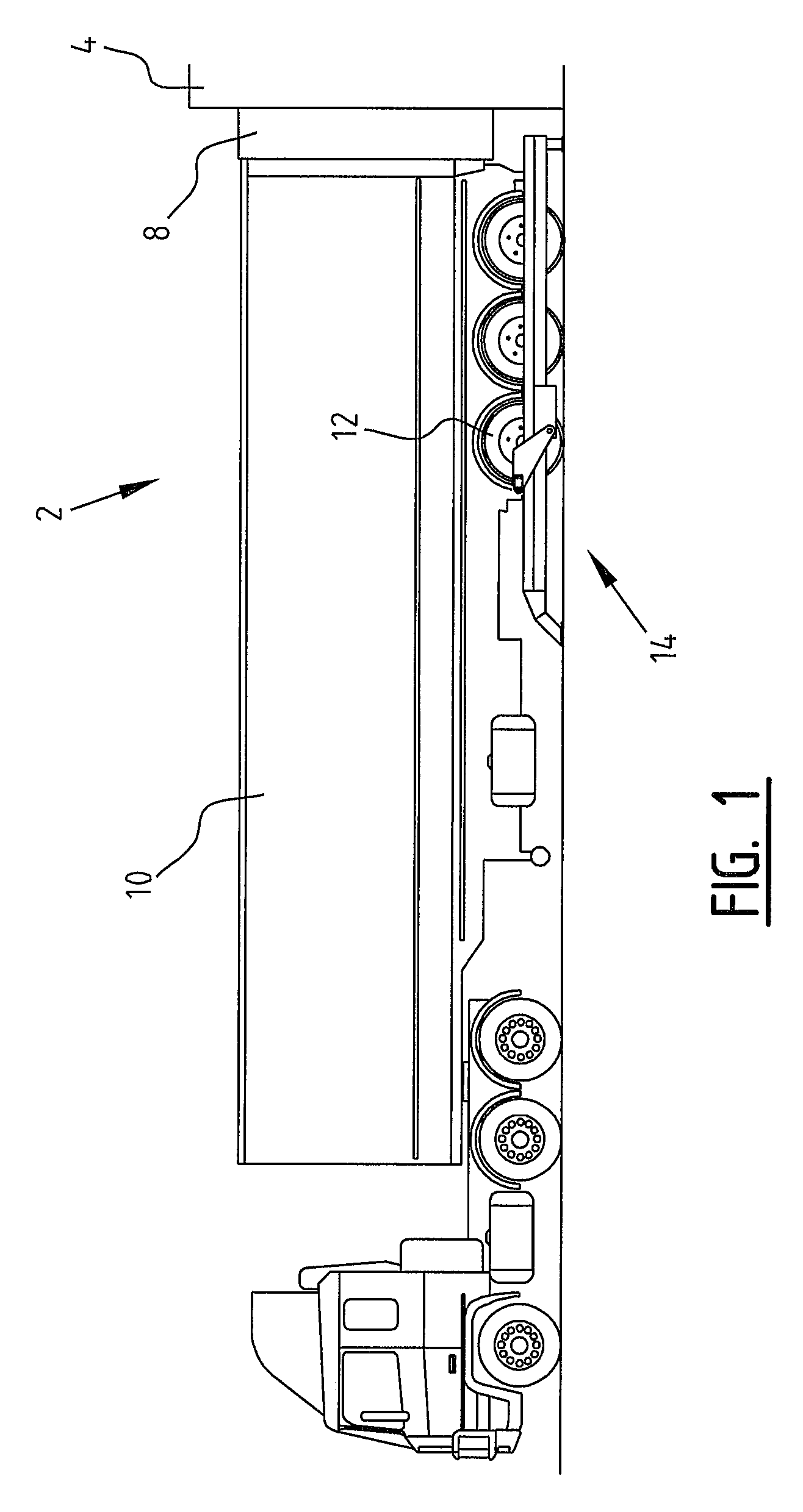
[0047]A loading-unloading location 2 (FIG. 1) is provided at a building 4. Each loading-unloading location 2 is provided with an opening or door 6 and a so-called dock shelter 8 for protection thereof. A truck 10 is reversed to loading-unloading location 2, inter alia with rear wheels 12. Truck 10 moves here substantially parallel to blocking device 14.

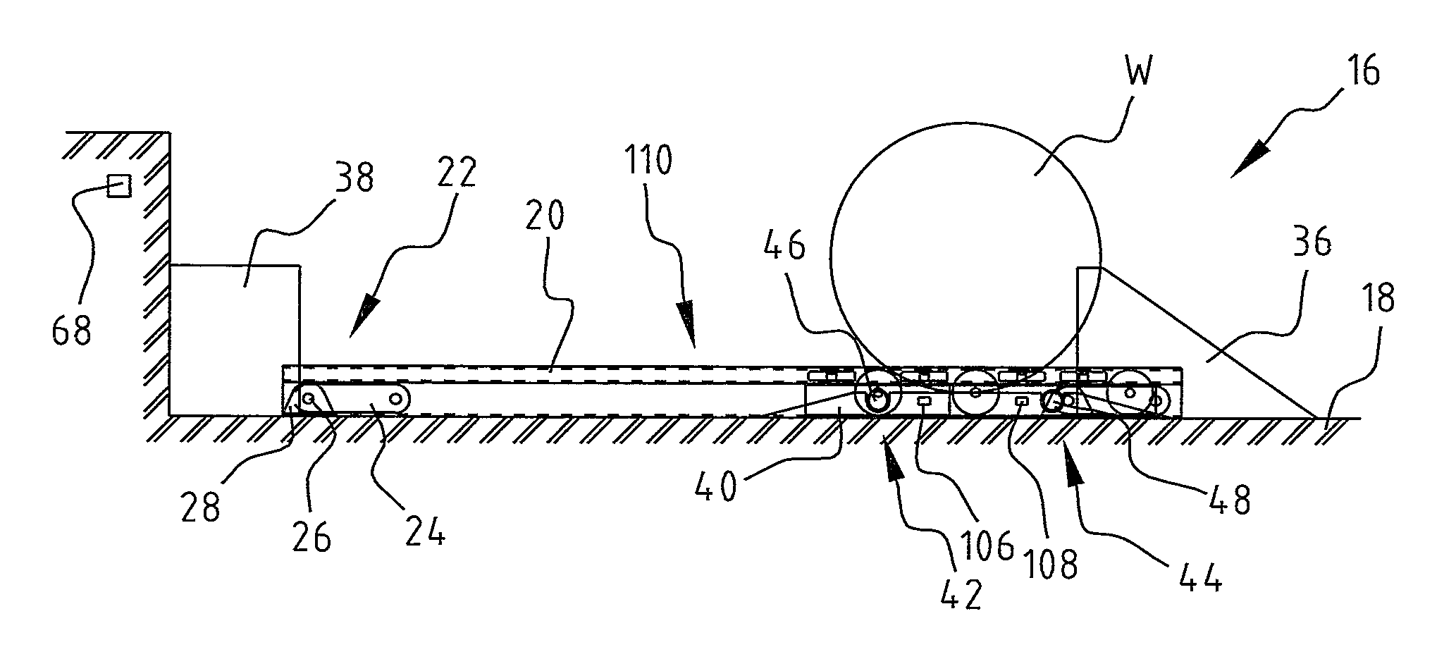
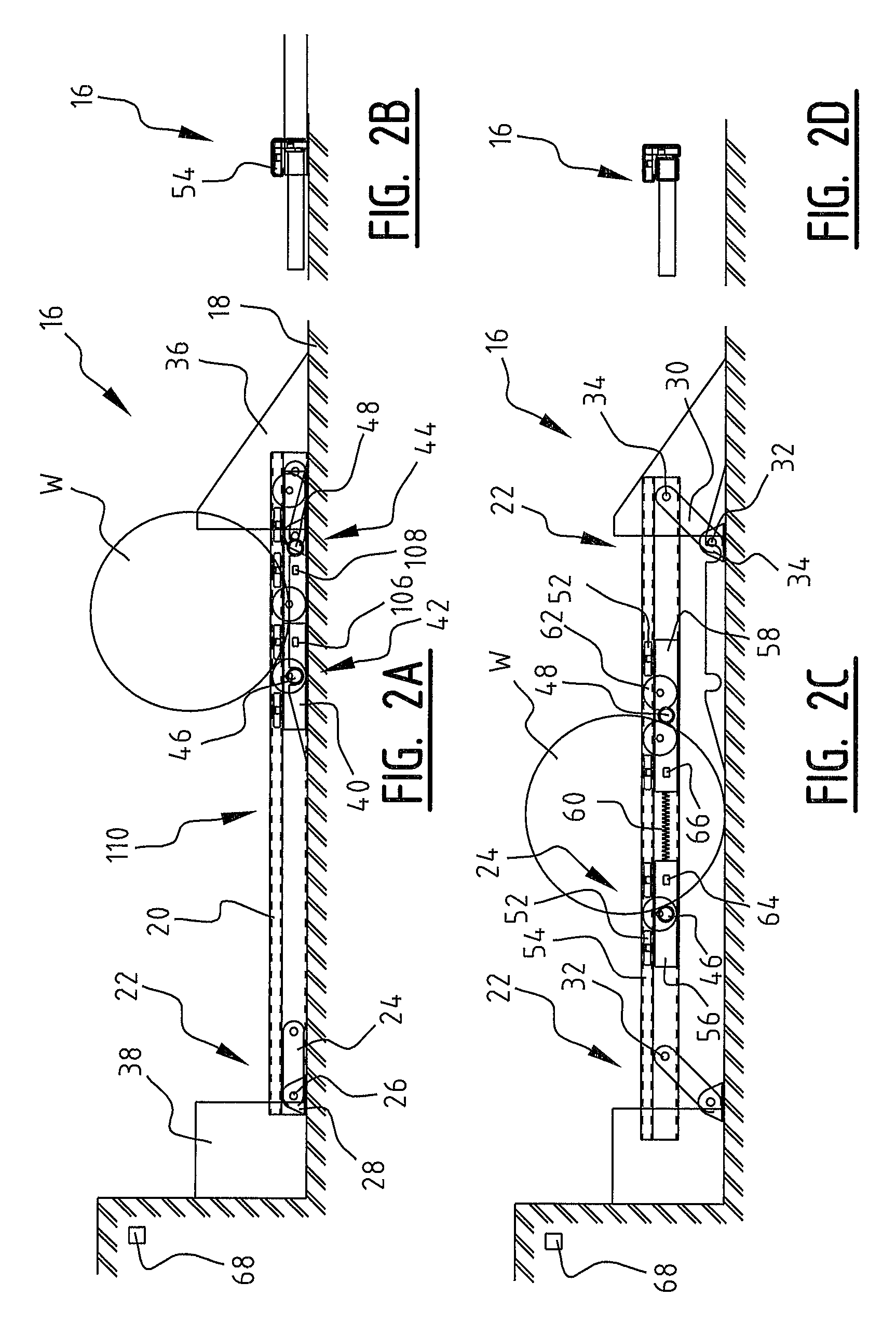
[0048]A blocking device 16 (FIG. 2A-F) is placed on the ground surface 18. Device 16 is provided with guide track 20 which in the shown embodiment can be adjusted in the height relative to ground surface 18 using height-adjusting means 22. Height-adjusting means 22 comprise an arm 24, which is connected to support 28 on ground surface 18 using rotation shaft 26, and a second arm 30 which is connected to second support 34 on ground surface 18 using second rotation shaft 32. At the other outer ends the arms 24, 30 are connected via respective rotation shafts 32, 34 to guide track 20.

[0049]Provided in the shown embodiment on the front si...


PUM


Abstract

Disclosed is a device for blocking a vehicle, a method making use of such a device and a loading-unloading station provided therewith. The device includes a guide track disposed along a driveway, a blocking component for blocking a wheel of the vehicle, and height-adjusting component for height adjustment of the guide track and / or the blocking component during use. The device preferably includes an anti-roll mode, wherein the blocking component engages at a first height, and a locking mode, wherein the blocking component engages at a second, greater height.

Description

CROSS REFERENCE TO RELATED APPLICATION[0001]This application claims the benefit of Netherlands Patent Application No. 2009050 entitled “Device for Blocking a Vehicle, Method Therefore and Loading-Unloading Station Provided Therewith” filed Jun. 21, 2012, which is hereby incorporated by reference in its entirety.BACKGROUND OF THE INVENTION[0002]1. Field of the Invention[0003]The present invention relates to a device for blocking a vehicle such as a truck. Such devices are generally used in practice to block a truck during loading and unloading thereof, for instance at a loading-unloading station of a distribution centre.[0004]2. Description of Related Art[0005]Devices for blocking trucks are per se known and are for instance described in EP 1 120 371 and EP 0 684 915. The blocking device known herefrom makes use of a drive to displace a carriage over a guide track. As soon as the truck is positioned correctly relative to the loading-unloading station a blocking means is extended and / ...

Claims


Application Information

Patent Timeline
Patent Type & Authority Patents(United States)
IPC IPC(8): B65G69/00
CPCB65G69/005B60P3/073
Inventor DE JONG, JURJEN JAN
Owner STERTIL
Why Eureka
Try Eureka