

Cutting insert with evolutive wedge or clearance angle and toolholder using such a cutting insert
a cutting insert and angle technology, applied in the field of cutting inserts, can solve the problems of cutting edge strength and cost, and achieve the effect of substantial cutting edge strength and facilitate the cutting of workpieces
- Summary
- Abstract
- Description
- Claims
- Application Information
AI Technical Summary
Benefits of technology
Problems solved by technology
Method used
Image

Examples
Embodiment Construction
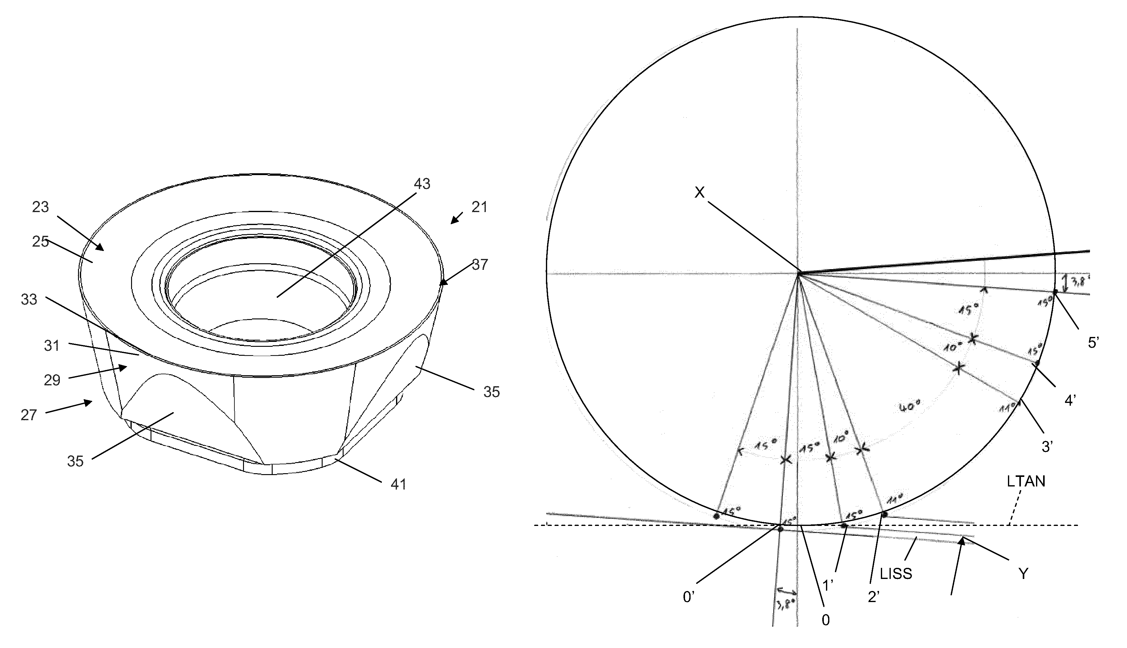
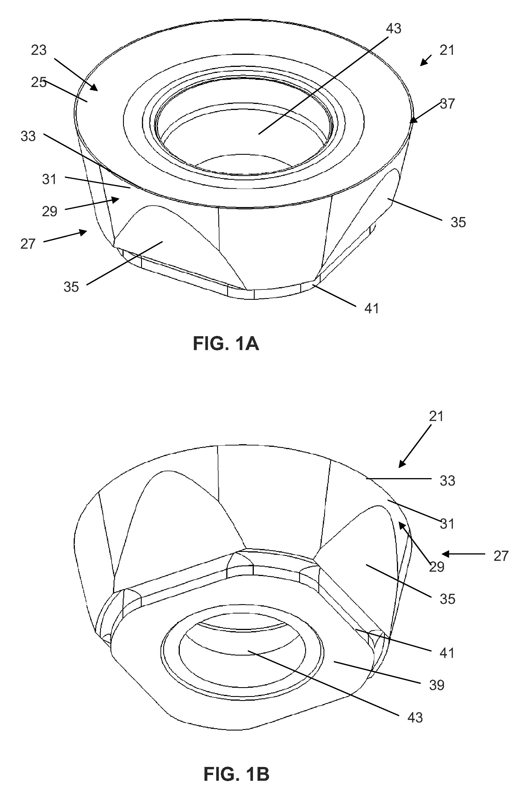
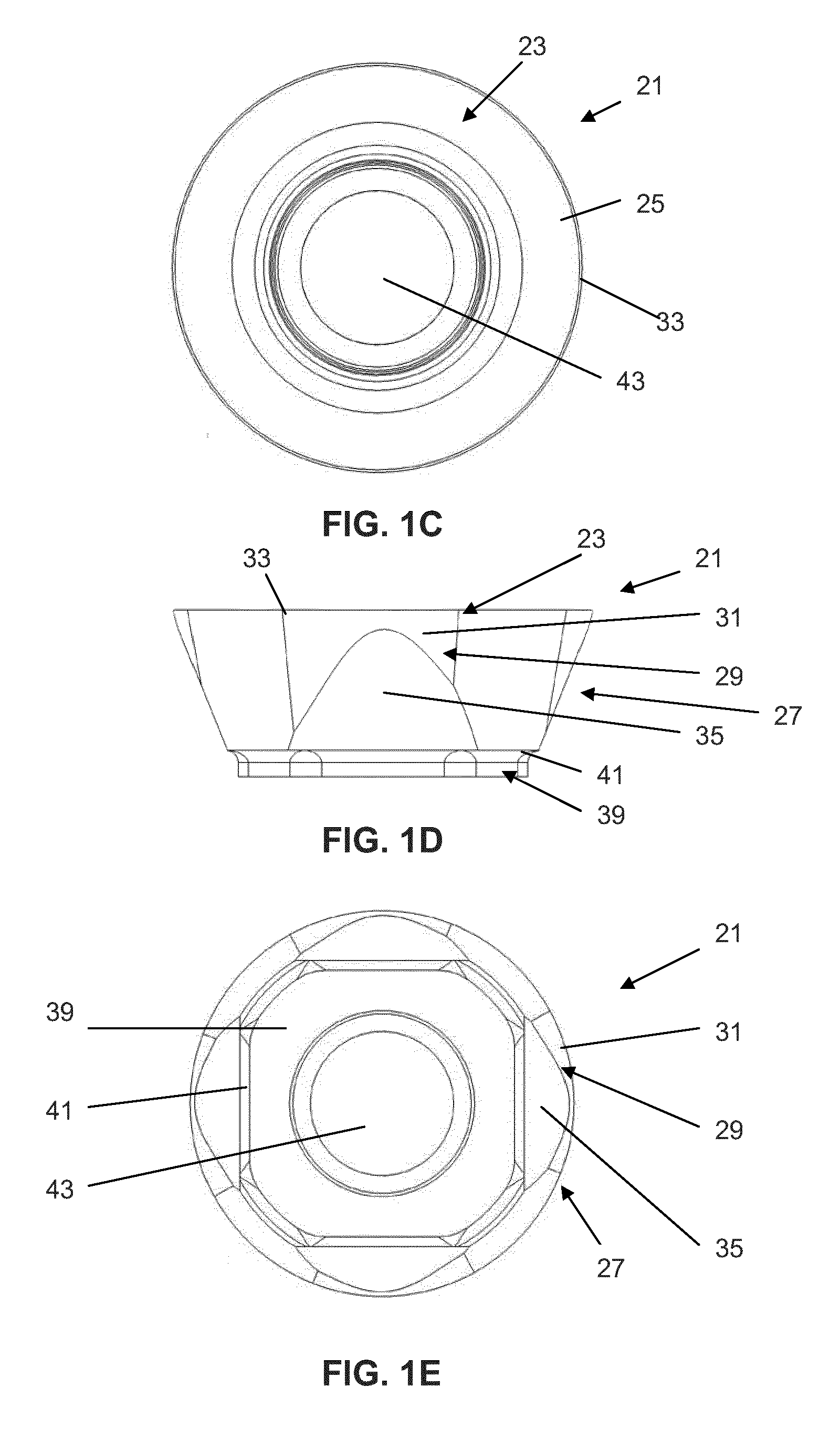
[0020]FIGS. 1A-1E show a circular cutting insert 21 according to an aspect of the present invention. The insert 21 can be made of a material such as cemented carbide and can be used for metal machining operations, however, other materials can be used to form the insert, and the insert can be used for operations other than metal machining.
[0021]The insert 21 comprises a top surface 23 including a top edge portion 25, a side surface 27 including a clearance surface 29 and a clearance edge portion 31, and a cutting edge 33 between the clearance edge portion and the top edge portion. The cutting edge 33 will ordinarily lie substantially on a reference plane (P, FIG. 2B), however, the cutting edge may have a variety of other shapes so that parts extend above or below a reference plane. The clearance edge portion 31 and the top edge portion 25 are those portions of the clearance surface 29 and the top surface 23, respectively, immediately proximate the cutting edge 33. Often, but not alwa...
PUM
 Abstract
Description
Claims
Application Information