System and method for reducing combustion dynamics and NOx in a combustor

a combustion dynamics and nox technology, applied in mechanical equipment, machines/engines, lighting and heating apparatus, etc., can solve the problems of increasing the production of carbon monoxide and unburned hydrocarbons, severe damage to the nozzle in a relatively short amount of time, and the chemical reaction rate of combustion gases, etc., to achieve the effect of reducing combustion dynamics and nox in the combustor

Active Publication Date: 2015-11-17
GENERAL ELECTRIC CO
View PDF55 Cites 11 Cited by
  • Summary
  • Abstract
  • Description
  • Claims
  • Application Information

AI Technical Summary

Benefits of technology

[0007]One embodiment of the present invention is a system for reducing combustion dynamics and NOx in a combustor. The system includes a tube bundle that extends radially across at least a portion of the combustor, wherein the tube bundle comprises an upstream surface axially separated from a downstream surface. A shroud circumferentially surrounds the upstream and downstream surfaces. A plurality of tubes extends through the tube bundle from the upstream surface through the downstream surface, wherein the downstream surface is stepped to prevent flame interaction between tubes and to produce tubes having different lengths through the tube bundle.

Problems solved by technology

However, higher combustion gas temperatures also promote flashback or flame holding conditions in which the combustion flame migrates towards the fuel being supplied by the nozzles, possibly causing severe damage to the nozzles in a relatively short amount of time.
Conversely, a lower combustion gas temperature associated with reduced fuel flow and / or part load operation (turndown) generally reduces the chemical reaction rates of the combustion gases, increasing the production of carbon monoxide and unburned hydrocarbons.
Increased vibrations in the combustor associated with high frequencies may reduce the useful life of one or more combustor components.
Alternately, or in addition, high frequencies of combustion dynamics may produce pressure pulses inside the premixer tubes and / or combustion chamber that affect the stability of the combustion flame, reduce the design margins for flashback or flame holding, and / or increase undesirable emissions.

Method used


Image

  • System and method for reducing combustion dynamics and NO<sub>x </sub>in a combustor
  • System and method for reducing combustion dynamics and NO<sub>x </sub>in a combustor
  • System and method for reducing combustion dynamics and NO<sub>x </sub>in a combustor

Examples


second embodiment

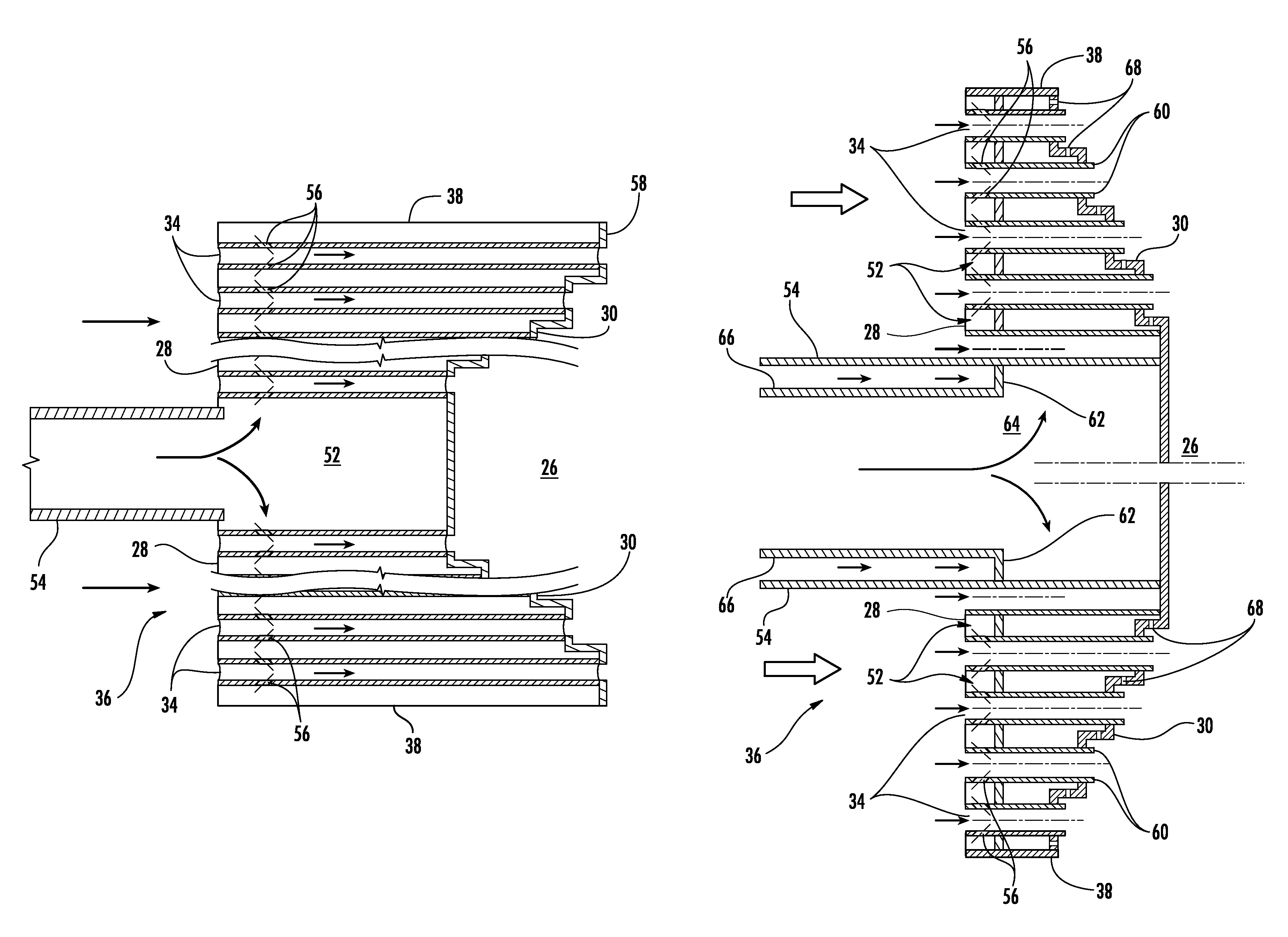
[0030]FIG. 6 provides an enlarged cross-section view of the tube bundle 36 according to the present invention. The tube bundle 36 again includes the upstream surface 28, downstream surface 30, plurality of tubes 34, shroud 38, fuel plenum 52, fuel conduit 54, and fuel ports 56 as previously described with respect to the embodiment shown in FIG. 5. As shown in this particular embodiment, one or more of the tubes 34 includes an extension 60 or protrusion downstream from the downstream surface 30. The tube extensions 60 or protrusions further assist in modifying flow instabilities downstream from the downstream surface 30 in the combustion chamber 26.

third embodiment

[0031]FIG. 7 provides an enlarged cross-section view of the tube bundle 36 according to the present invention. The tube bundle 36 again includes the upstream surface 28, downstream surface 30, plurality of tubes 34, shroud 38, fuel plenum 52, fuel conduit 54, and fuel ports 56 as previously described with respect to the embodiments shown in FIGS. 5 and 6. In addition, a barrier 62 extends radially inside the tube bundle 36 between the upstream and downstream surfaces 28, 30 to separate the fuel plenum 52 from a diluent plenum 64 inside the tube bundle 36. A diluent conduit 66 may extend from the casing 12 and / or end cover 14 through the upstream surface 28 separately from the fuel conduit 54 or coaxially with the fuel conduit 54, as shown in FIG. 7, to provide fluid communication for a diluent to flow into the diluent plenum 64. Suitable diluents include, for example, water, steam, combustion exhaust gases, and / or an inert gas such as nitrogen. A plurality of diluent ports 68 throug...

fourth embodiment

[0032]FIG. 8 provides an enlarged cross-section view of the tube bundle 36 according to the present invention. This particular embodiment generally represents a combination of the embodiments previously described and illustrated with respect to FIGS. 6 and 7. As a result, the tube bundle 36 includes the upstream surface 28, downstream surface 30, plurality of tubes 34, shroud 38, fuel plenum 52, fuel conduit 54, fuel ports 56, tube extensions 60, barrier 62, diluent plenum 64, diluent conduit 66, and diluent ports 68 as previously described with respect to the embodiments shown in FIGS. 6 and 7. As shown in this particular embodiment, the stepped shape of the downstream surface 30 is convex, with the shorter axial lengths between the upstream and downstream surfaces 28, 30 towards the perimeter of the tube bundle 36.


PUM


Abstract

A system for reducing combustion dynamics and NOx in a combustor includes a tube bundle that extends radially across at least a portion of the combustor, wherein the tube bundle comprises an upstream surface axially separated from a downstream surface. A shroud circumferentially surrounds the upstream and downstream surfaces. A plurality of tubes extends through the tube bundle from the upstream surface through the downstream surface, wherein the downstream surface is stepped to produce tubes having different lengths through the tube bundle. A method for reducing combustion dynamics and NOx in a combustor includes flowing a working fluid through a plurality of tubes radially arranged between an upstream surface and a downstream surface of an end cap that extends radially across at least a portion of the combustor, wherein the downstream surface is stepped.

Description

FEDERAL RESEARCH STATEMENT[0001]This invention was made with Government support under Contract No. DE-FC26-05NT42643, awarded by the Department of Energy. The Government has certain rights in the invention.FIELD OF THE INVENTION[0002]The present invention generally involves a system and method for reducing combustion dynamics and NOx in a combustor.BACKGROUND OF THE INVENTION[0003]Combustors are commonly used in industrial and power generation operations to ignite fuel to produce combustion gases having a high temperature and pressure. For example, gas turbines typically include one or more combustors to generate power or thrust. A typical gas turbine used to generate electrical power includes an axial compressor at the front, one or more combustors around the middle, and a turbine at the rear. Ambient air may be supplied to the compressor, and rotating blades and stationary vanes in the compressor progressively impart kinetic energy to the working fluid (air) to produce a compresse...

Claims


Application Information

Patent Timeline
Patent Type & Authority Patents(United States)
IPC IPC(8): F23R3/02F23M20/00F23R3/00F23L7/00F23R3/28
CPCF23R3/002F23L7/005F23M20/005F23R3/283F23D2900/00018F23L2900/07002F23R2900/00014
Inventor UHM, JONG HOJOHNSON, THOMAS EDWARD
Owner GENERAL ELECTRIC CO
Why Eureka
Try Eureka