Stepped swirler for dynamic control

a swirler and dynamic control technology, applied in mechanical equipment, machines/engines, light and heating equipment, etc., can solve problems such as time-consuming fretting or component failure, and achieve the effect of reducing or decreasing the width

Inactive Publication Date: 2014-03-25
SIEMENS AG
View PDF19 Cites 2 Cited by
  • Summary
  • Abstract
  • Description
  • Claims
  • Application Information

AI Technical Summary

Benefits of technology

[0017]In conventional systems, it may be tried to produce a homogeneous exhaustion of a mixture of air and fuel by using ducts or passages each comprising similar and fixed dimension. With the claimed invention, the depth of the first duct and the second duct may be different which will have the effect of altering the exhaust of a medium between each of the ducts and thus within the central passage. This may also alter the burning characteristic which produces a smaller area of flame which furthermore may burn with a lower level of noise. The reduced combustion dynamics leading to improved component life.
[0029]According to a further exemplary embodiment, the swirling device further comprises a control unit. The control unit is adapted for controlling the medium volume and pressure in at least one of the first ducts and the second ducts. The control unit may for instance control the medium volume and the medium pressure that is injected by the liquid injection portion or the gas injection portion. Furthermore, the control unit may control the width and the depth of the first ducts and the second ducts. For instance, in one exemplary embodiment, the first ducts and the second ducts may be formed by swirler vanes that may be adjustable placed to the swirling device. Thus, by moving the swirler vanes, a desired width and / or a desired depth of the first and second ducts may be provided. Hence, the control unit may adjust a desired flow pattern of the medium in the swirling device, in particular in the central passage.

Problems solved by technology

While running on liquid fuel, the combustion system produces high levels of combustion dynamics, such as pressure changes of a fuel, changes in the flow direction of the fuel air mixture and flame dynamics, which may cause over a period of time fretting or component failure.

Method used


Image

  • Stepped swirler for dynamic control
  • Stepped swirler for dynamic control
  • Stepped swirler for dynamic control

Examples


Embodiment Construction

[0035]The illustration in the drawing is schematically. It is noted that in different figures, similar or identical elements are provided with the same reference signs or with reference signs, which are different from the corresponding reference signs only within the first digit.

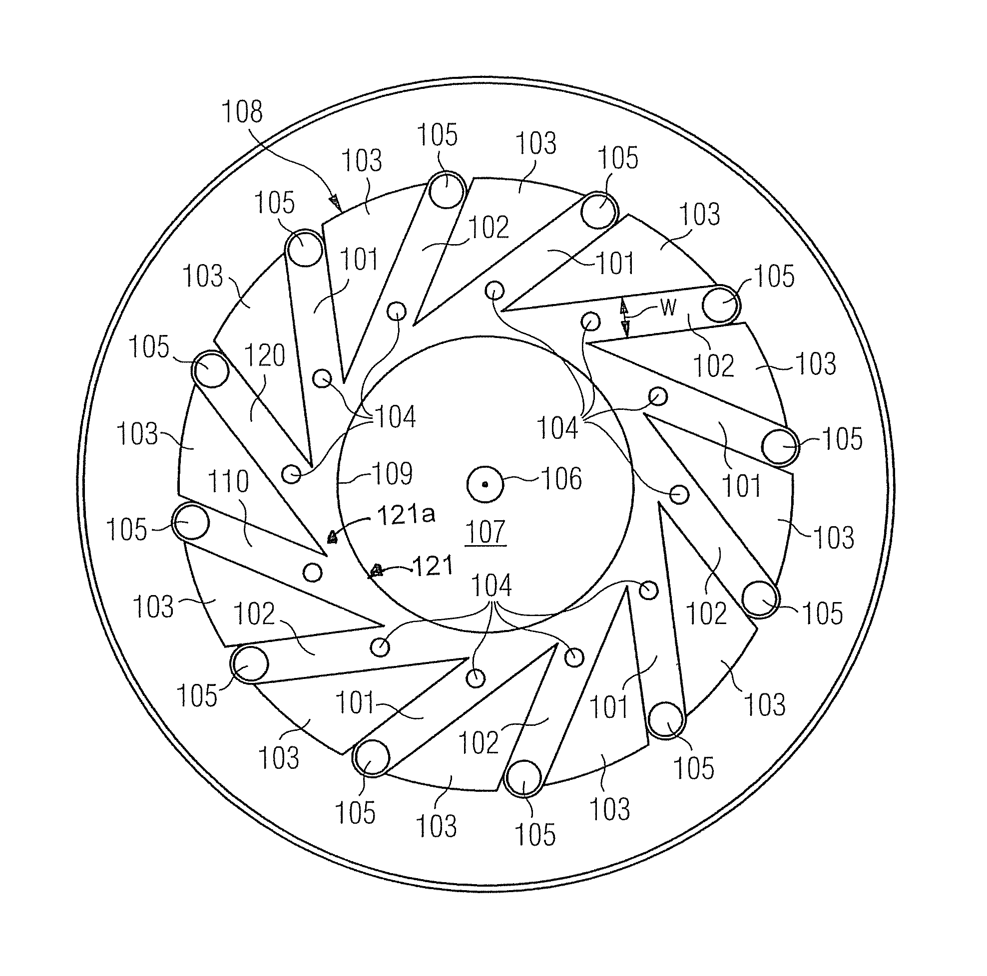
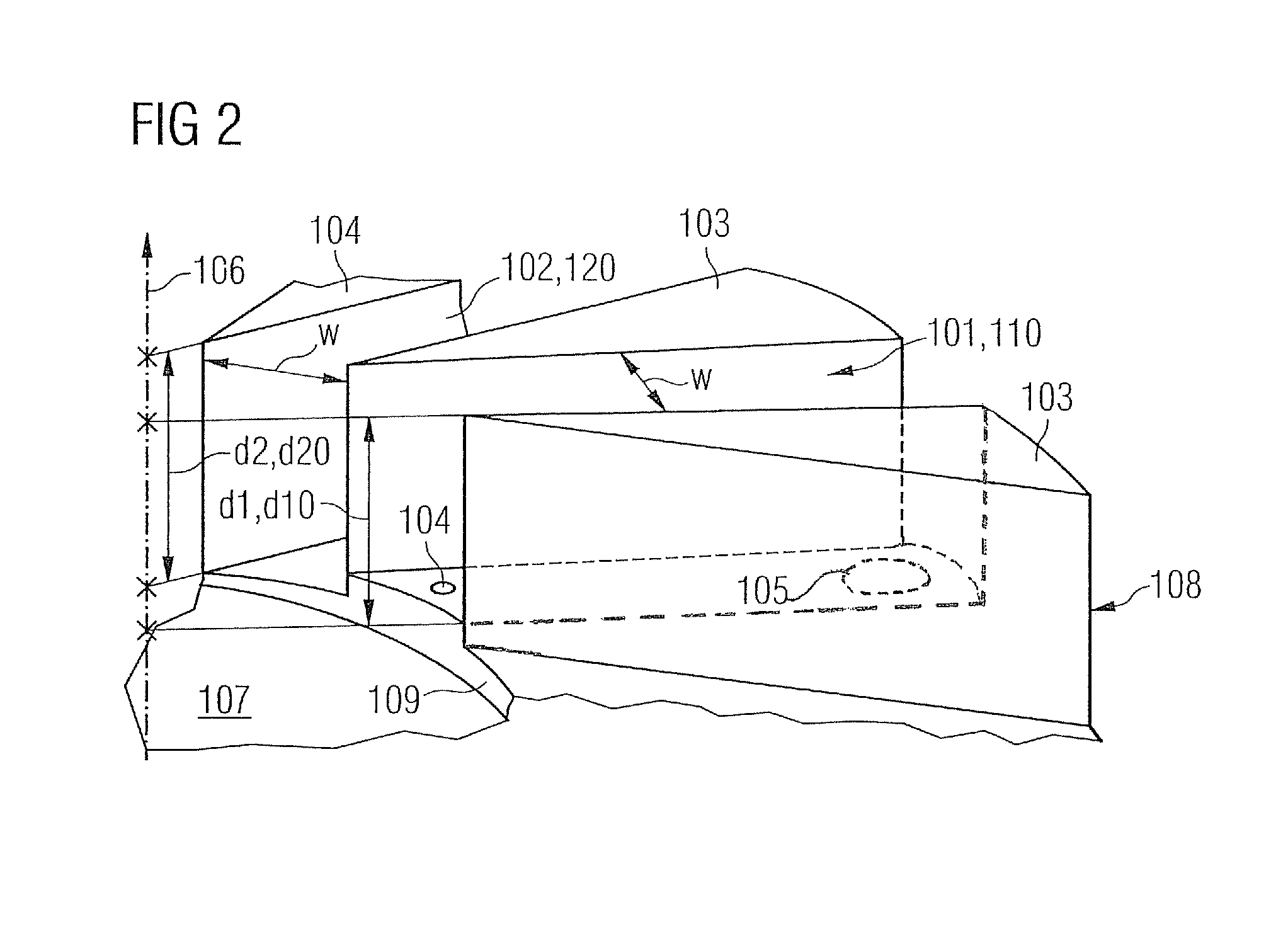
[0036]FIG. 1 shows a swirling device 100 for injecting a medium into a turbine. The swirling device 100 comprises a central axis 106, a central passage 107 in an axial direction along the centre axis 106 and an outer perimeter 108. The swirling device 100 further comprises a first duct 101 and a second duct 102. The first duct 101 and the second duct 102 are adapted for guiding the medium from a region surrounding the outer perimeter 108 to the central passage 107. The first duct 101 comprises a first depth d1 in the axial direction and the second duct 102 comprises a second depth d2 in the axial direction. The first depth d1 and the second depth d2 are different.

[0037]Furthermore, FIG. 1 shows a swirling de...


PUM


Abstract

A swirling device for injecting a medium into a turbine is provided. The swirling device includes a central axis, a central passage in an axial direction along the central axis and an outer perimeter. The swirling device further includes a first duct and a second duct. The first duct and the second duct are adapted for guiding the medium from a region surrounding the outer perimeter to the central passage. The first duct includes a first depth in the axial direction and the second duct includes a second depth in the axial direction. The first depth and the second depth are different.

Description

CROSS REFERENCE TO RELATED APPLICATIONS[0001]This application is the US National Stage of International Application No. PCT / EP2009 / 060144, filed Aug. 5, 2009 and claims the benefit thereof. The International Application claims the benefits of European Patent Office application No. 08016915.4 EP filed Sep. 25, 2008. All of the applications are incorporated by reference herein in their entirety.FIELD OF INVENTION[0002]The present invention relates to the field of fuel injectors for gas turbine engines. In particular, the present invention relates to a swirling device for injecting a medium into a turbine. Moreover, the present invention relates to a method of injecting a medium into a turbine.ART BACKGROUND[0003]In order to provide turbines a more efficient gas turbine there may be a need to reduce high levels of fluid dynamic during injection of a gas / fuel mixture into a combustion system of a turbine. While running on liquid fuel, the combustion system produces high levels of combus...

Claims


Application Information

Patent Timeline
Patent Type & Authority Patents(United States)
IPC IPC(8): F02G3/00B05B7/10B05B1/34F02C1/00
CPCF23R2900/00014F23C2900/07001F23R3/14F23D2900/14701F23R3/286
Inventor HUBBARD, PHILLIP
Owner SIEMENS AG
Why Eureka
Try Eureka