Hole arrangement of liners of a combustion chamber of a gas turbine engine with low combustion dynamics and emissions

a gas turbine engine and combustion chamber technology, applied in the direction of machines/engines, mechanical equipment, lighting and heating apparatus, etc., can solve the problems of promoting combustion instabilities, and achieve the effect of reducing combustion instabilities and lowering emissions

Inactive Publication Date: 2015-04-16
SIEMENS AG
View PDF7 Cites 2 Cited by
  • Summary
  • Abstract
  • Description
  • Claims
  • Application Information

AI Technical Summary

Benefits of technology

[0009]It may be an object of the present invention to provide a combus

Problems solved by technology

However, directing more air flow through the front end, the combustion chamber promotes com

Method used


Image

  • Hole arrangement of liners of a combustion chamber of a gas turbine engine with low combustion dynamics and emissions
  • Hole arrangement of liners of a combustion chamber of a gas turbine engine with low combustion dynamics and emissions
  • Hole arrangement of liners of a combustion chamber of a gas turbine engine with low combustion dynamics and emissions

Examples


Embodiment Construction

[0042]The illustrations in the drawings are schematical. It is noted that in different figures, similar or identical elements are provided with the same reference signs.

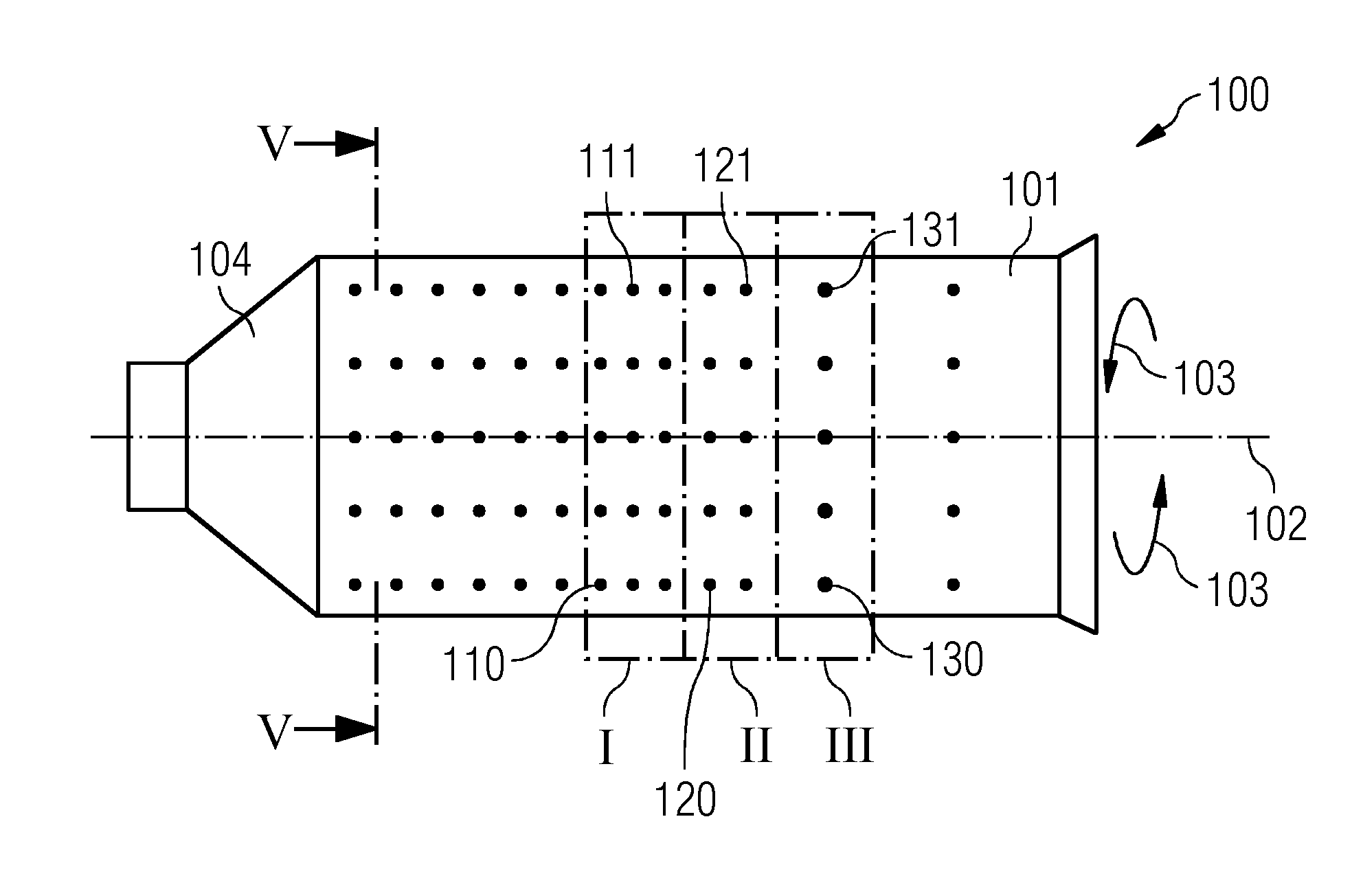
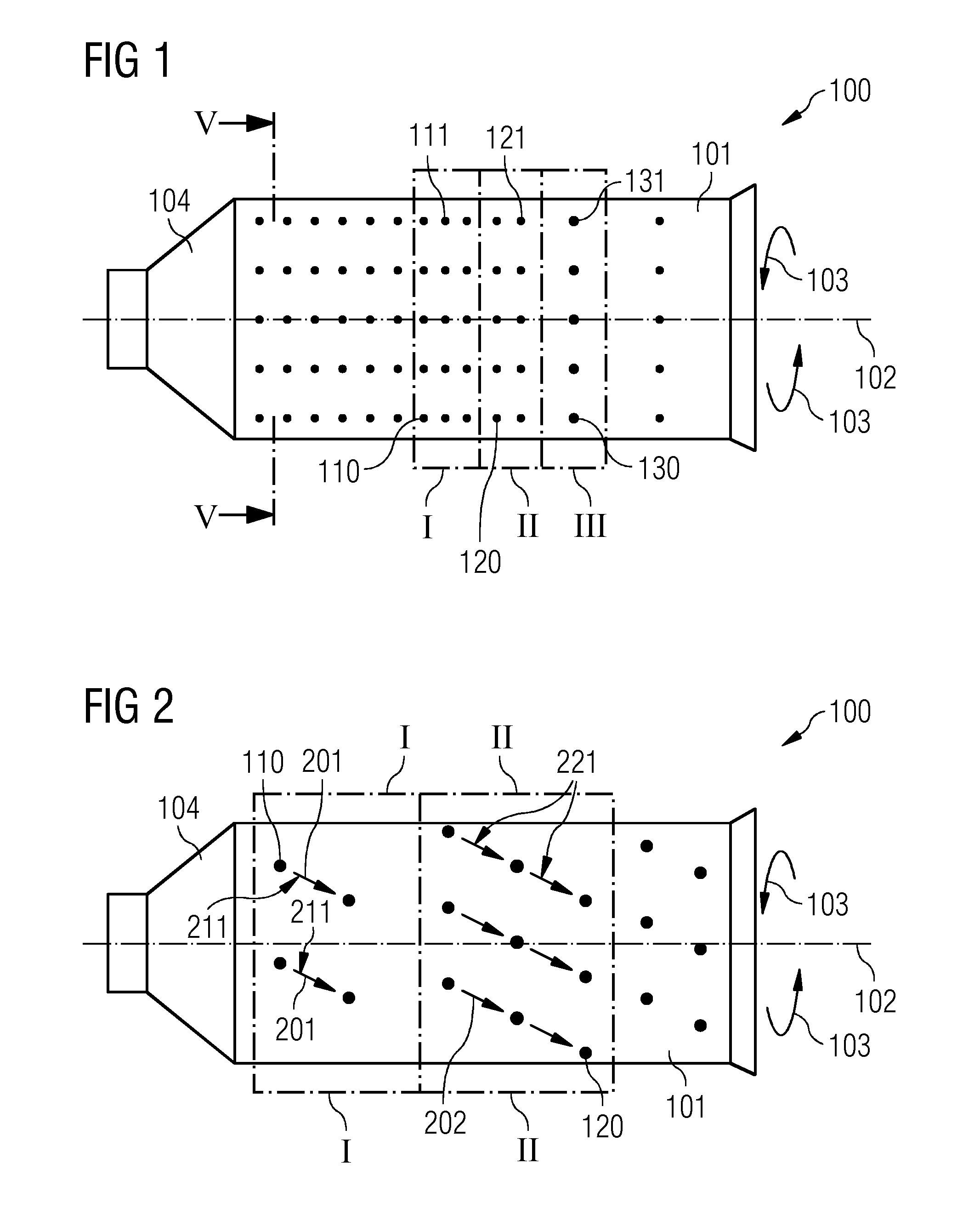
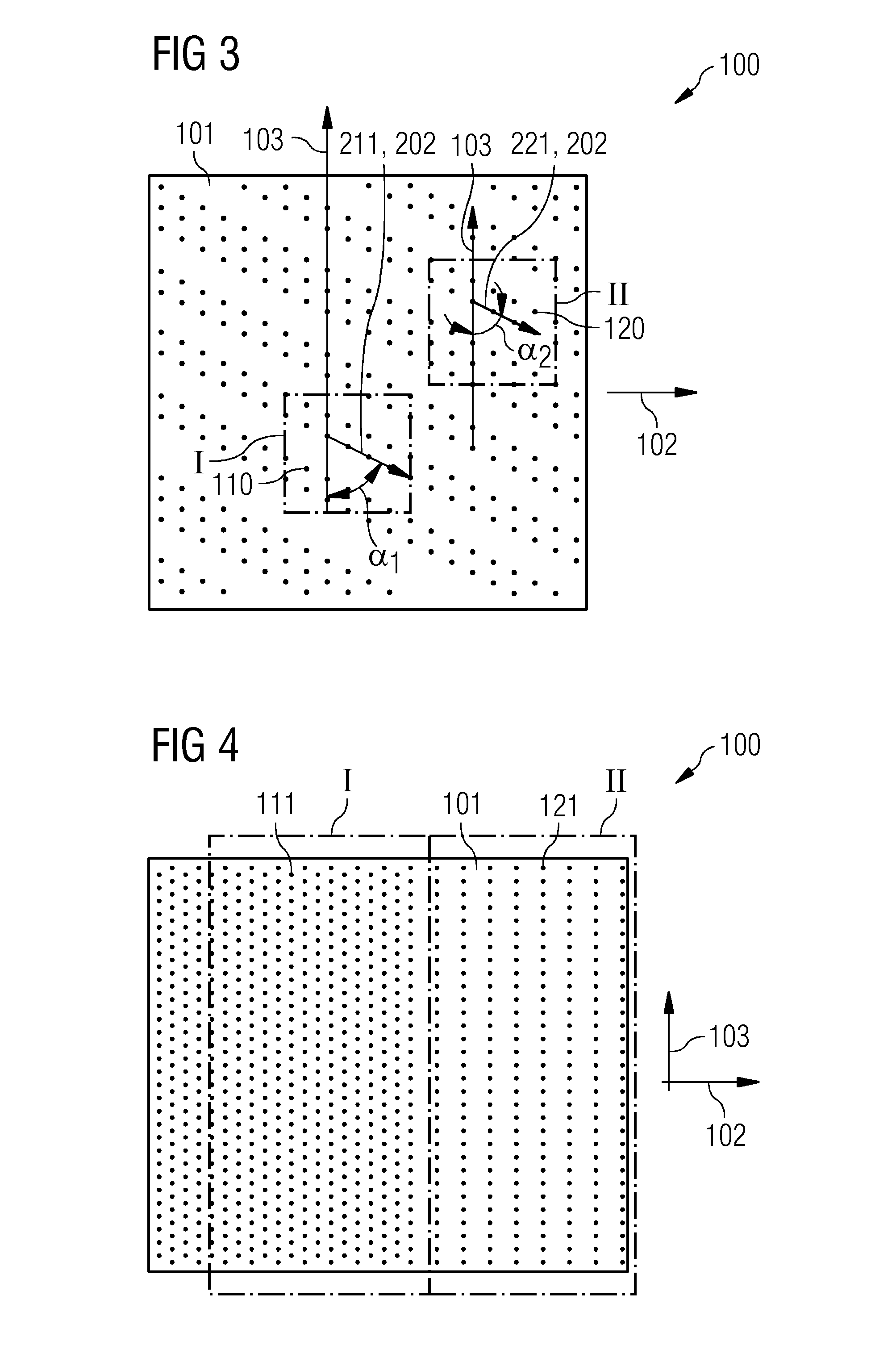
[0043]FIG. 1 shows a housing for a combustion chamber 100 for a gas turbine. The housing comprises a wall element 101 which comprises a first hole arrangement I and a second hole arrangement II. The first hole arrangement I comprises first holes 110 through which first holes 110 fluid is streamable. The first hole arrangement I comprises a first areal density of the first holes 110.

[0044]The second hole arrangement II comprises second holes 120 through which second holes 120 fluid is streamable. The second hole arrangement II comprises a second areal density of the second holes 120.

[0045]The first areal density differs from the second areal density. That is that the amount of first holes 110 per area unit differs from the amount of second holes 120 per area unit. In other words, the first holes 110 are distributed wi...


PUM

PropertyMeasurementUnit
Timeaaaaaaaaaa
Angleaaaaaaaaaa
Angleaaaaaaaaaa

Abstract

A gas turbine combustion chamber with an inner housing and an outer housing the inner housing having an inner wall element with a first hole arrangement and a second hole arrangement is provided. The inner wall element envelopes a burner volume. The first hole arrangement has first holes arranged in a first areal density, the second hole arrangement has second holes arranged in a second areal density. The outer housing has an outer wall element with a further first hole arrangement and a further second hole arrangement. The outer wall element of the outer housing envelops the inner wall element of the inner housing so that a gap in between is formed. The further first hole arrangement has further first holes arranged in a further first areal density, the further second hole arrangement has further second holes arranged in a further second areal density.

Description

CROSS REFERENCE TO RELATED APPLICATIONS[0001]This application is the US National Stage of International Application No. PCT / EP2012 / 074459 filed Dec. 5, 2012, and claims the benefit thereof. The International Application claims the benefit of European Application No. EP 12161509 filed Mar. 27, 2012. All of the applications are incorporated by reference herein in their entirety.FIELD OF INVENTION[0002]The present invention relates to a housing for a combustion chamber for a gas turbine and to a method for producing a combustion chamber of a gas turbine.ART BACKGROUND[0003]In a field of gas turbine technology it is an aim to reduce the production of environmental pollutants such as various oxides of nitrogen (NOx), carbon monoxide (CO) and unburned hydrocarbons (UHC). Therefore, it is an aim to achieve a reliable and stable lean-burn combustion process in a combustion chamber of a gas turbine.[0004]In order to provide a lean-burn combustion process more air is directed in particular cl...

Claims


Application Information

Patent Timeline
IPC IPC(8): F23R3/04F23R3/42F23R3/00
CPCF23R3/04F23R3/002F23R3/42F23R2900/03044F23R3/06F23R3/44F23R2900/00014F23R2900/03041Y10T29/49229
Inventor JAYATUNGA, CHARITH
Owner SIEMENS AG
Why Eureka
Try Eureka