A method of holding flame with no combustion instability, low pollutant emissions, least pressure drop and flame temperature in a gas turbine combustor and a gas turbine combustor to perform the method

a gas turbine combustor and flame temperature technology, applied in the direction of combustion process, lighting and heating apparatus, charge feed system, etc., can solve the problems of increasing flame temperature, reducing the overall efficiency of the engine, and high pressure loss, so as to improve combustion efficiency, reduce nox emissions, and stabilize against higher velocities

Active Publication Date: 2019-10-03
INDIAN INST OF TECH MADRAS
View PDF0 Cites 4 Cited by
  • Summary
  • Abstract
  • Description
  • Claims
  • Application Information

AI Technical Summary

Benefits of technology

[0011]Yet in other aspect the invention shows that fuel is distributed through many of these swirlers and injected directly into the combustor with each swirler with injection operating in overall lean conditions. The flames that are stabilized from them interact very closely and thus help each other stabilize against higher velocities. This, in turn, increases combustion efficiency. The flames need to burn only small amount of fuel each and thus are very short, but are distributed along the liner. This gives very low NOx emissions due to low residence times in high temperature zone. The distributed flame also helps reduce combustion instability problems in combustors. Since high temperature zones are reduced, and the air is flowing through most areas of the liner, the heat transfer to the liner will be lower and thus it does not need thermal protection. This decreases weight of the combustion chamber in an engine. The distribution of air through various locations in the liner is dictated by the swirler distribution and fuel distribution is dictated by the injection distribution in the swirlers. This gives a good handle on the final temperature distribution in the combustor exit and to avoid large pattern factors.
[0012]Another aspect of the invention relates to fuel distribution across different locations of the burner allowing the fuel-air-ratio to be in a very lean range, decreasing the pollutant emissions without affecting flame holding.
[0013]Wherein, the fuel is injected into either the center of each of the swirlers, or at the periphery between adjacent swirlers, or both. This has an advantage of having lower pollutant emissions as the flame temperature is lowered and the residence time for air in high temperature zone is lesser. The wall thickness of the swirler vanes can be higher than usual in this arrangement since there are not much pressure losses otherwise. This combustor also has the advantage of a variety of choices of fuel injection locations for part load operations. This option further gives an active control option for combustion instability as one has different fuel flow rates for different injectors. This distributed combustion along with variability in fuel injection patterns helps decrease combustion instability in the combustor.
[0014]Wherein, the said flame holding is used in gas turbine engine combustors at high flow velocities providing good flame stabilization.
[0015]Wherein, the proposed burner may also have some other applications in industrial oil / gas fired furnaces and many gas turbine engine companies are interested in flame holdings that have the advantages of low pollutant emissions and no combustion instability.

Problems solved by technology

These swirlers have very small passages between them for the flow of air and thus have high pressure losses.
These pressure losses lead to lesser efficiency of the engine on the whole.
However, this increases the flame temperature and thus the NOx emissions along with increase in combustor weight due to thermal protection linings.
The approach in the past to decrease the pollutants is to burn a little leaner, causing the flame to be more susceptible to combustion instability.
There are a few designs which have multiple swirler assemblies in the head end of the combustor, which may have a lesser pressure drop in the head end due to area change, along with lower combustion instability.

Method used


Image

  • A method of holding flame with no combustion instability, low pollutant emissions, least pressure drop and flame temperature in a gas turbine combustor and a gas turbine combustor to perform the method
  • A method of holding flame with no combustion instability, low pollutant emissions, least pressure drop and flame temperature in a gas turbine combustor and a gas turbine combustor to perform the method
  • A method of holding flame with no combustion instability, low pollutant emissions, least pressure drop and flame temperature in a gas turbine combustor and a gas turbine combustor to perform the method

Examples


Embodiment Construction

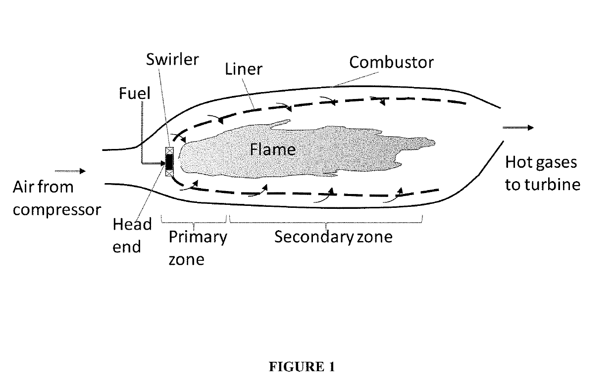
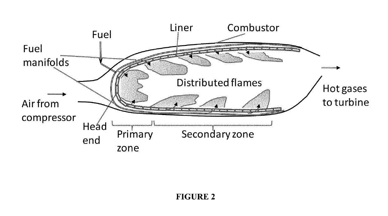
[0024]The present invention relates to a new method for flame holding in gas turbine combustors with least pressure drop and flame temperature.

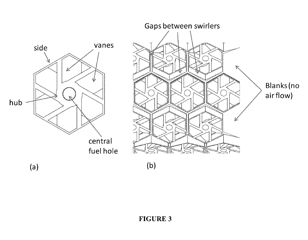
[0025]An aspect of the invention relates to turbine engine combustor having swirlers in a hexagonal packing arrangement, minimizing solid mass between the swirlers with minimal pressure loss.

[0026]One aspect of the invention relates to a direct fuel distribution using swirl mesh lean injection for flame holding.

[0027]Another aspect of the invention relates to fuel distribution across different locations of the burner allowing the fuel-air-ratio to be in a very lean range, decreasing the pollutant emissions without affecting flame holding.

[0028]Wherein, the fuel is injected into either the center of each of the swirlers, or at the periphery between adjacent swirlers, or both. This has the advantage of having lower pollutant emissions as the flame temperature is lowered and the residence time for air in high temperature zone is lesser. This com...


PUM


Abstract

A swirl mesh lean direct injection concept for distributed flame holding for low pollutant emissions and mitigation of combustion instability. The invention further relates to a new method for flame holding with least pressure drop and flame temperature, in gas turbine engine combustors, wherein the liner of the combustor is partially or fully replaced with a “swirl mesh”. The invention has lean direct injection for fuel distribution over several points in gas turbine combustors along with swirl arrangement for air injection which provides low pollutant emission and low combustion instability.

Description

CROSS REFERENCE TO RELATED APPLICATIONS[0001]This U.S. patent application is a national stage of International Application PCT / IN2017 / 050291 filed on Jul. 14, 2017, which in turn claims benefits to Indian Provisional Patent Application IN 201641024206 filed on Jul. 15, 2016.FIELD OF THE INVENTION[0002]The present invention relates to a means for distribution of air and fuel, more particularly relates to an arrangement of swirlers, flame holders, burners etc., to provide well distributed flame in gas turbine engine combustor systems.BACKGROUND OF THE INVENTION[0003]A combustor also known as a burner, combustion chamber or flame holder is a component or area of a gas turbine, ramjet, or scramjet engine and designed to help maintain continual combustion. Combustors play a crucial role in determining many of an engine operating characteristics, such as fuel efficiency, levels of emissions and transient response (the response to changing conditions such a fuel flow and air speed). The up...

Claims


Application Information

Patent Timeline
Patent Type & Authority Applications(United States)
IPC IPC(8): F02C7/22F23R3/12
CPCF23R3/12F02C7/222F05D2240/35F23R3/02F23R3/06F23R3/14F23R2900/00014F23R3/34F23R3/28F23R3/286
Inventor MURUGANANDAM, T. M.CHAKRAVARTHY, S. R.PREETHI, R. S.RAJABHARATHI, N.DEEPIKA, V.SHANMUGAPRABHU, S.
Owner INDIAN INST OF TECH MADRAS
Why Eureka
Try Eureka