Split exhaust engine with idle check valve

A technology for engines and engine loads, applied to engine components, combustion engines, engine control, etc., can solve problems such as reducing combustion stability, fuel economy and combustion stability, and increasing exhaust residues

Pending Publication Date: 2019-10-11
FORD GLOBAL TECH LLC
View PDF0 Cites 0 Cited by
  • Summary
  • Abstract
  • Description
  • Claims
  • Application Information

AI Technical Summary

Problems solved by technology

This valve overlap period can negatively impact fuel economy and combustion stability at light engine loads
Although the period of valve overlap can be reduced or eliminated at low loads by advancing exhaust valve timing, the resulting loss of exhaust valve opening can reduce fuel economy, negating any potential benefit of reduced valve overlap
On the other hand, if the exhaust valve timing is retarded to reduce exhaust valve losses, internal exhaust residues may increase, reducing combustion stability

Method used


Image

  • Split exhaust engine with idle check valve
  • Split exhaust engine with idle check valve
  • Split exhaust engine with idle check valve

Examples


Embodiment Construction

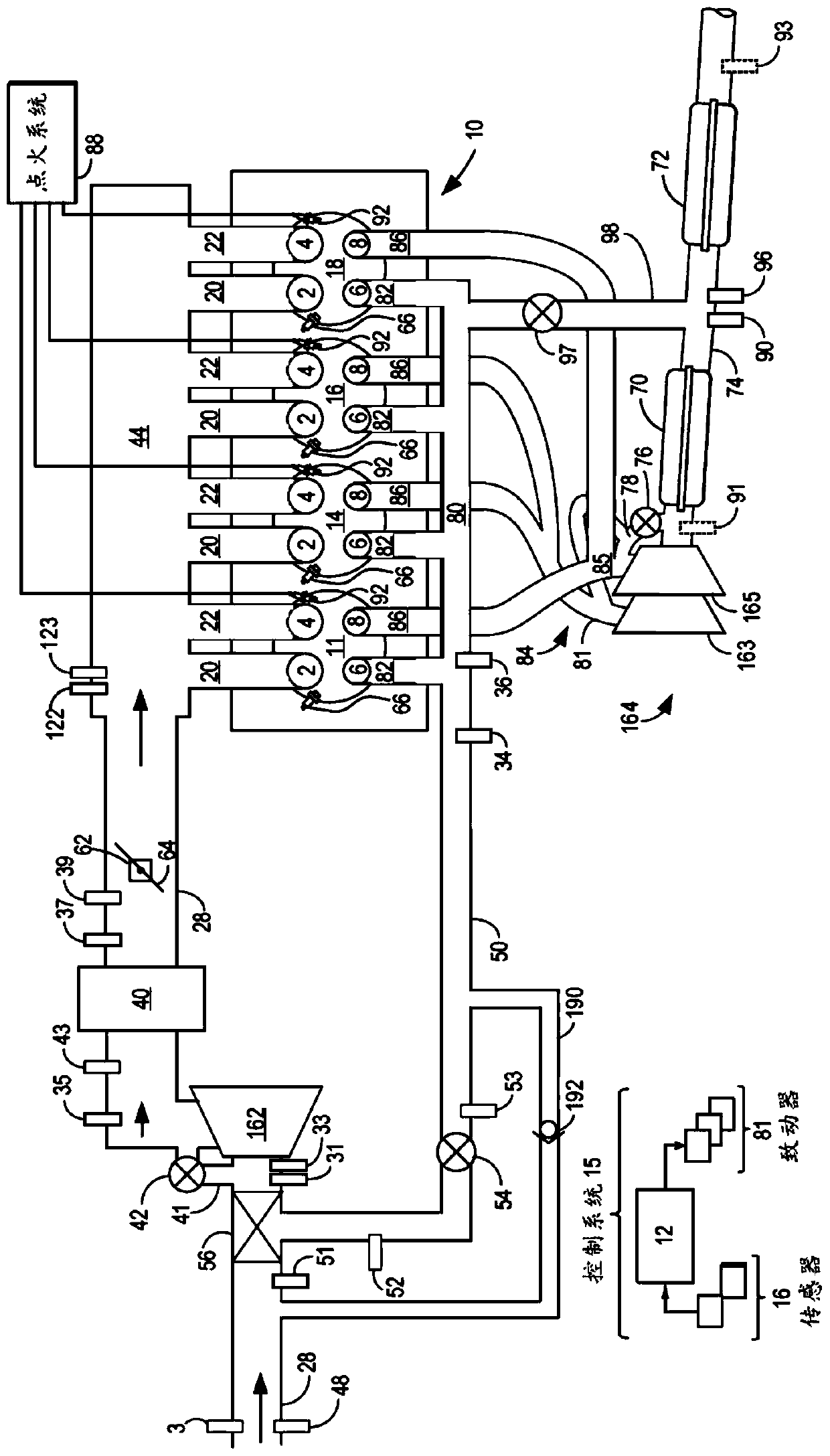
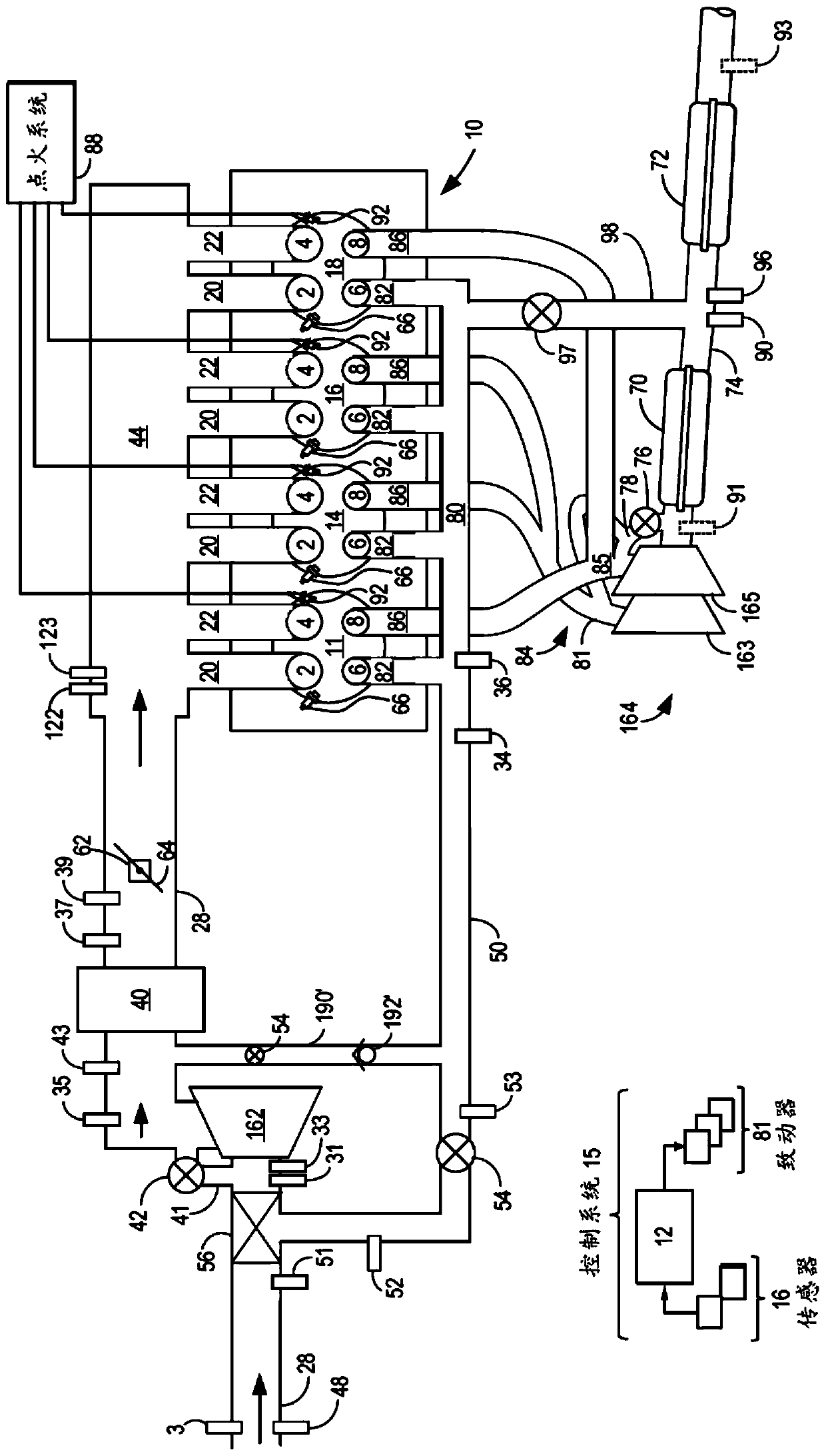
[0016] The following description relates to systems and methods for operating a split exhaust engine with direct blowing and exhaust gas recirculation (EGR) via a scavenged exhaust manifold to an intake passage. Such as Figure 1A and Figure 1B As shown in , the split exhaust engine includes a first exhaust manifold (referred to herein as the blown exhaust manifold) coupled only to the blown exhaust valves of each cylinder. The blow-off manifold is coupled to an exhaust passage of the engine, wherein the exhaust passage includes a turbocharger turbine and one or more emission control devices (which may include one or more catalysts). Split exhaust engines also include a second exhaust manifold (referred to herein as a scavenged exhaust manifold) that is coupled only to the scavenged exhaust valves of each cylinder. The scavenging manifold is coupled to the intake passage upstream of the turbocharger compressor via an EGR passage that includes an EGR valve (referred to herein...


PUM


Abstract

The disclosure provides a split exhaust engine with an idle check valve. Methods and systems are provided for reducing exhaust residuals during light load conditions in a split exhaust engine via a check valve. In one example, a scavenge exhaust manifold may be maintained above a threshold pressure by introducing fresh air into the scavenge manifold during a valve overlap period, the scavenge manifold coupled to a cylinder of an engine and coupled to an intake passage of the engine.

Description

technical field [0001] The present specification generally relates to methods and systems for increasing combustion stability and reducing exhaust valve opening losses in split exhaust engine operation utilizing direct injection. Background technique [0002] The engine may use a boosting device, such as a turbocharger, to increase engine power density. However, engine knock may occur due to elevated combustion temperatures. Knocking is especially problematic under supercharged conditions due to the high charge temperature. The inventors herein have realized that knocking can be reduced and engine efficiency can be improved by using an engine system with a split exhaust system in which a first exhaust manifold recirculates exhaust gas (EGR) The compressor upstream of the exhaust manifold directs the exhaust to the intake passage of the engine, and the second exhaust manifold directs exhaust gas to the turbine of the turbocharger in the exhaust passage of the engine. In su...

Claims


Application Information

Patent Timeline
IPC IPC(8): F02D41/00F02D13/02F02D41/08
CPCF02D13/0249F02D41/0002F02D41/0077F02D41/08F02D2041/001F01N13/107F02B37/183F02D13/0257F02D13/0261F02D41/0007F02D41/005F02D41/006F02D41/0065F02M26/43Y02T10/12Y02T10/40F02D35/027F02D41/0052F02D41/0055F02D41/0057F02D41/086F02M26/08F02M2026/005
Inventor 约瑟夫·乌雷约翰·埃里克·米卡埃尔·赫尔斯特伦丹尼尔·麦迪逊克里斯多夫·约翰·派珀安德烈斯·塞瓦洛斯
Owner FORD GLOBAL TECH LLC
Why Eureka
Try Eureka