Ablative baffle for a liquid rocket engine thrust chamber

a technology of liquid rocket engine and thrust chamber, which is applied in the direction of rocket engine plants, machines/engines, jet propulsion plants, etc., can solve the problems of affecting the reliability affecting the operation of liquid rocket engine, and high probability of specific frequency combustion instability of the thrust chamber, so as to reduce the probability of combustion instability

Inactive Publication Date: 2005-05-12
KOREA AEROSPACE RES INST
View PDF7 Cites 13 Cited by
  • Summary
  • Abstract
  • Description
  • Claims
  • Application Information

AI Technical Summary

Benefits of technology

[0010] An object of the present invention is to provide an ablative baffle for a liquid rocket engine thrust chamber, which has the capability of reduction of combustion instability by a predetermined geometrical shape.

Problems solved by technology

Such liquid rocket engine thrust chamber has high probability of combustion instability of specific frequencies in the spectrum, which may be generated during combustion inside combustion chamber.
Generation of combustion instability and amplification thereof cause fatal problem of engine failure and worsen the reliability of liquid rocket engine.
However, the technique has a problem that a baffle is melted or damaged because it is mounted inside combustion chamber where high temperature and high pressure combustion gas are resided.
When combustion instability occurs, even other apparatuses and parts, which are connected with an engine, could be damaged.
This method has a problem that a manufacturing method is complicated and additional pressurizing device to inject propellant at high pressure is needed.
Furthermore, the system of engine and entire launch vehicle may become complicated.
This method has a fatal problem of thickening tank walls in order to endure high pressure, which increases the weight of tank and the weight of launch vehicle and decrease the performance of launch vehicle.

Method used


Image

  • Ablative baffle for a liquid rocket engine thrust chamber
  • Ablative baffle for a liquid rocket engine thrust chamber
  • Ablative baffle for a liquid rocket engine thrust chamber

Examples


Embodiment Construction

[0041] Hereinafter, referring to the following appended drawings, the preferred embodiments of the present invention will be explained in detail.

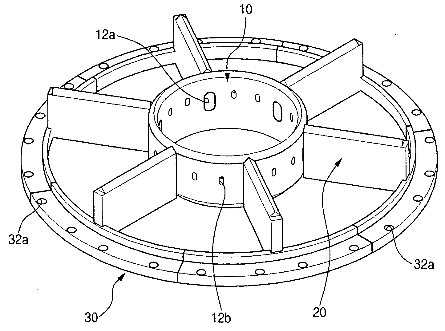
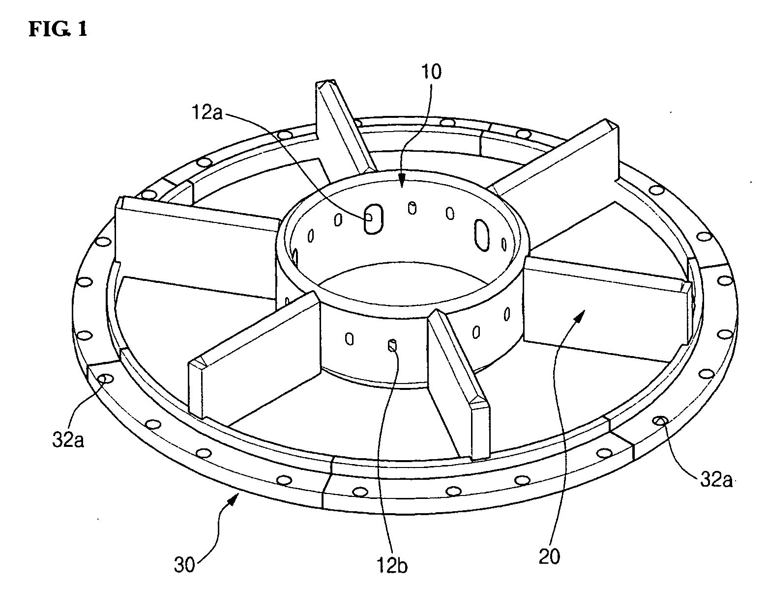
[0042]FIG. 1 is the perspective view of an ablative baffle for a liquid rocket engine thrust chamber according to the present invention, and FIG. 2 is the exploded perspective view of FIG. 1.

[0043] Referring to FIGS. 1 and 2, an ablative baffle for a liquid rocket engine thrust chamber according to the present invention comprises a hub member 10, a plurality of blade rib members 20, each of which is connected at one end to the outer surface of the hub member 10, and a blade-connecting member 30 to the inner part of which each of the blade rib members 20 is connected at the other end.

[0044] The hub member 10 has a hollow structure, of which the top and bottom parts are open.

[0045] Preferably, the hub member 10 has a ring shape.

[0046] The hub member 10 has a plurality of connecting holes 12a to each of which the blade rib member 20 is co...


PUM


Abstract

The present invention is related to an ablative baffle for a liquid rocket engine thrust chamber that comprises: a hub member having a hollow structure, of which both top and bottom parts are open; a plurality of blade rib members, each of which is connected removably at one end to the outer surface of the hub member; and a blade-connecting member having a hollow structure, of which both top and bottom parts are open, to the inner part of which each of blade rib members is connected at the other end. The present invention does not use a conventional internal cooling method, but an ablation cooling method using the composite heat resistant material structure with metal core, so that a liquid rocket engine system may be simplified, and the reliability of liquid rocket engine increases, and the manufacturing cost is cut down.

Description

FIELD OF THE INVENTION [0001] The present invention is related to an ablative baffle for a liquid rocket engine thrust chamber, and more particularly, to an ablative baffle for a liquid rocket engine thrust chamber, which has the capability of reducing the combustion instability of specific acoustic mode, which is generated during combustion inside combustion-chamber of liquid rocket engine thrust chamber. PRIOR ART [0002] A liquid rocket engine thrust chamber obtains thrust by ejecting high temperature and high pressure gas, which is produced from combustion of liquid propellant injected into combustion chamber. [0003] Such liquid rocket engine thrust chamber has high probability of combustion instability of specific frequencies in the spectrum, which may be generated during combustion inside combustion chamber. Generation of combustion instability and amplification thereof cause fatal problem of engine failure and worsen the reliability of liquid rocket engine. [0004] Recently, th...

Claims


Application Information

Patent Timeline
Patent Type & Authority Applications(United States)
IPC IPC(8): F02K1/06F02K9/34F02K9/42F02K9/62F02K9/95
CPCF02K9/34F02K9/62F02K9/42F02K1/06
Inventor RYU, CHULSUNGSEOL, WOOSEOKHAN, SANGYEOP
Owner KOREA AEROSPACE RES INST
Why Eureka
Try Eureka