Method and system for indicating water at an oxygen sensor based on sensor heater power consumption

An oxygen sensor, power consumption technology, used in charging systems, testing of machine/structural components, instruments, etc., to solve problems such as inaccurate adjustment of spark timing or other combustion parameters

Active Publication Date: 2018-11-23
FORD GLOBAL TECH LLC
View PDF4 Cites 0 Cited by
  • Summary
  • Abstract
  • Description
  • Claims
  • Application Information

AI Technical Summary

Problems solved by technology

In some examples, use of such inaccurate EGR measurements could trigger diagnostic routines, as well as inaccurately adjust spark timing or other combustion parameters

Method used


Image

  • Method and system for indicating water at an oxygen sensor based on sensor heater power consumption
  • Method and system for indicating water at an oxygen sensor based on sensor heater power consumption
  • Method and system for indicating water at an oxygen sensor based on sensor heater power consumption

Examples


Embodiment Construction

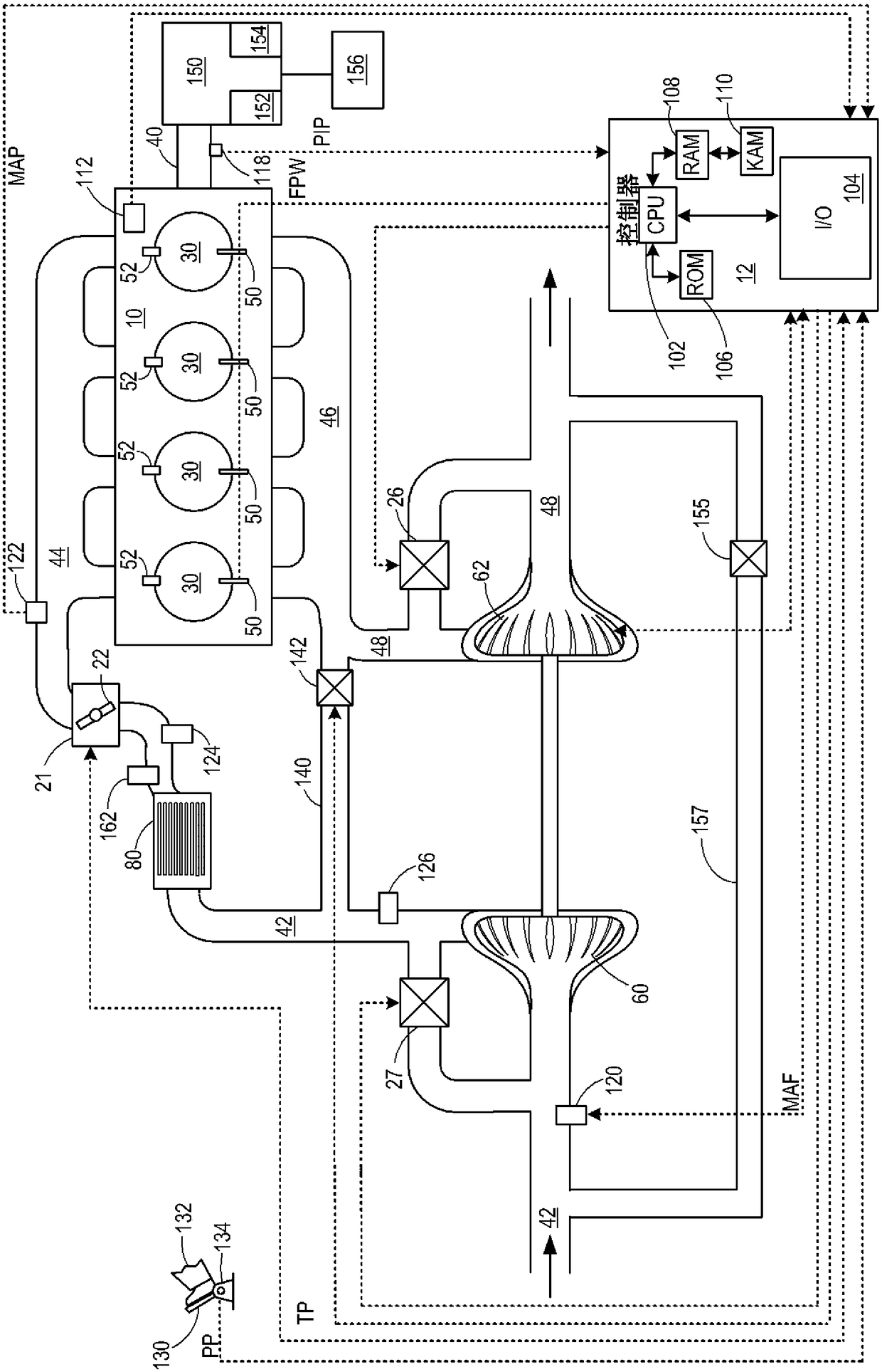
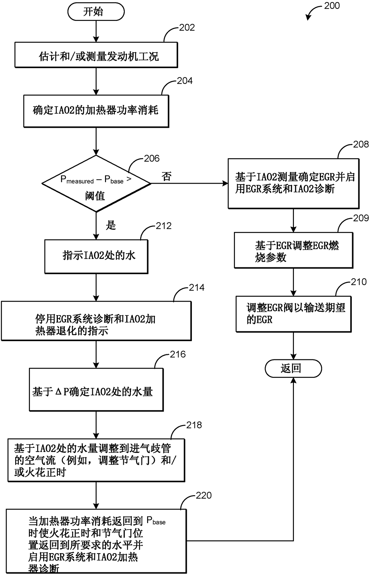
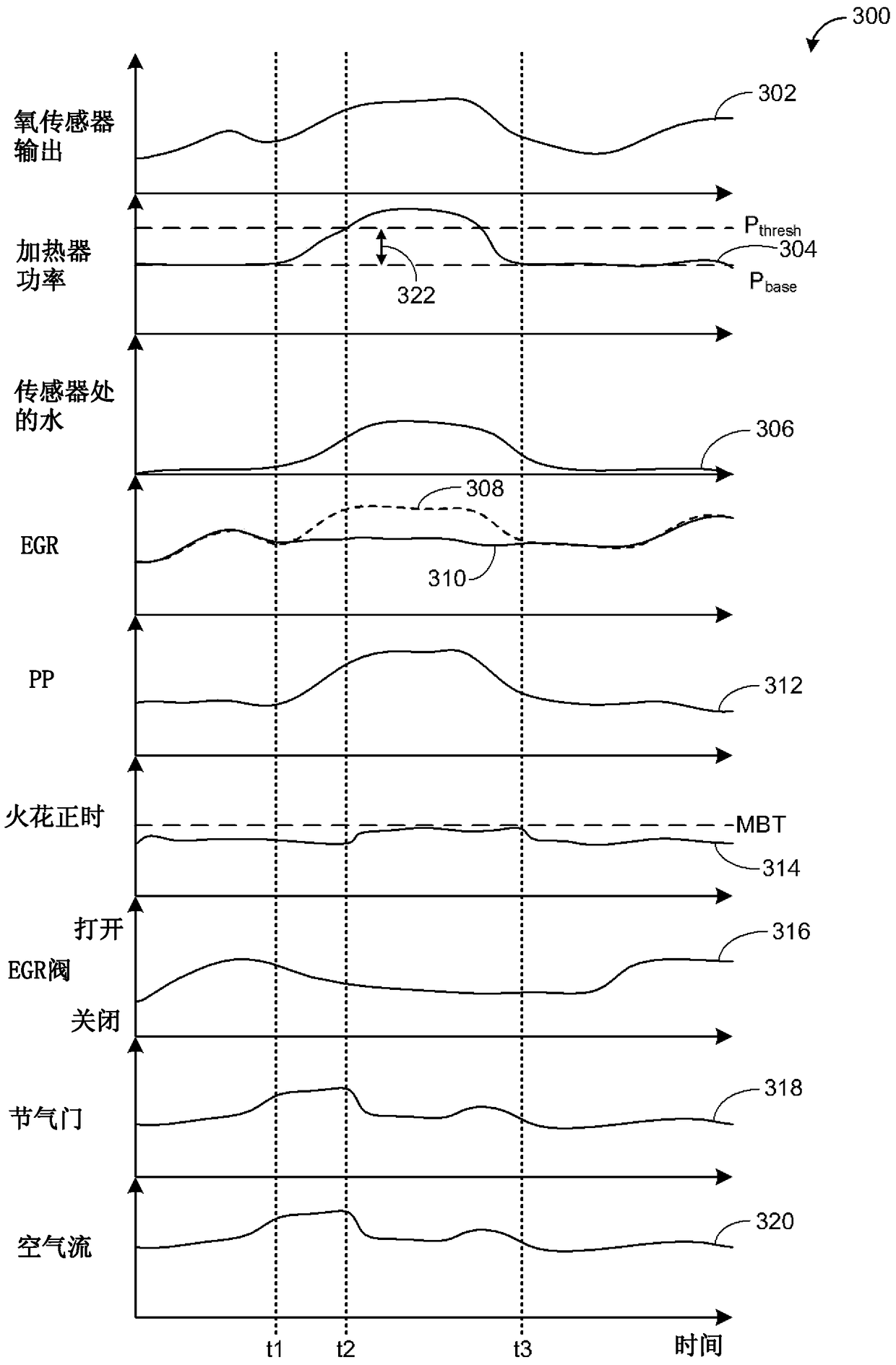
[0009] The following description relates to a system and method for indicating water at the oxygen sensor based on the power consumption of the heating element of the oxygen sensor. Specifically, the oxygen sensor can be set in the engine system (such as figure 1 Engine system) in the engine air intake device downstream of the charge air cooler (CAC). Therefore, the oxygen sensor may be referred to herein as an intake oxygen sensor (IAO2). When water (e.g., water droplets) contacts IAO2, the power consumption of the heating element (e.g., heater) of IAO2 can be increased in order to maintain the set point temperature of IAO2. Therefore, when power consumption increases to a threshold amount above the reference power consumption level, water at IAO2 can be indicated. figure 2 A method for adjusting engine operation based on the power consumption of the IAO2 heating element is shown. Specifically, in response to the water indication, the engine controller may adjust engine oper...


PUM


Abstract

The present invention relates to methods and systems for indicating water at an oxygen sensor based on power consumption of a sensor heater. Methods and systems are provided for indicating water at an oxygen sensor based on power consumption of a heating element of the oxygen sensor. In one example, water at the oxygen sensor may be indicated in response to power consumption of a heating element of the oxygen sensor increasing above a reference level, where the oxygen sensor is disposed in an engine intake. Engine operating parameters may then be adjusted based on the water indication and power consumption.

Description

Technical field [0001] This application relates to a method and system for indicating water at an oxygen sensor based on the power consumption of the sensor heater. Background technique [0002] The engine system may utilize the recirculation of exhaust gas from the engine exhaust system to the engine intake system (a process known as exhaust gas recirculation (EGR)) to reduce prescribed emissions. For example, a turbocharged engine system may include a low pressure (LP) EGR system, which recirculates exhaust gas from the exhaust system to the intake passage upstream of the turbocharger compressor. An intake oxygen sensor (IAO2) may be arranged in the engine intake device downstream of the compressor and charge air cooler to provide an indication of the EGR flow based on the measured water content of the intake air. [0003] The inventor here has recognized various problems with the above-mentioned system. Specifically, if water from another source contacts IAO2, the intake oxyge...

Claims


Application Information

Patent Timeline
Patent Type & Authority Patents(China)
IPC IPC(8): F02D43/00
CPCF02D41/0072F02D41/144F02D41/1494F02D41/1495F02P5/1502F02D41/0002F02M26/04F02M26/46F02M26/49F02B29/04F02M26/44F02D41/0007F02D2200/0418F02M2026/001F02M26/45Y02T10/40Y02T10/12F02D41/0065G01M15/02
Inventor G·苏尼拉R·E·索尔蒂斯D·A·马克德T·J·克拉克
Owner FORD GLOBAL TECH LLC
Why Eureka
Try Eureka