Radar device

a radar device and receiver technology, applied in the direction of measurement devices, using reradiation, instruments, etc., can solve the problems of affecting the accuracy of detection in which the radar device detects the target at a long distance, hardly obtained, and low range side lobe characteristics in the autocorrelation characteristics of the reception signal are not realized

Active Publication Date: 2015-12-15
PANASONIC INTELLECTUAL PROPERTY MANAGEMENT CO LTD
View PDF23 Cites 3 Cited by
  • Summary
  • Abstract
  • Description
  • Claims
  • Application Information

AI Technical Summary

Benefits of technology

[0029]According to the radar device of the invention, even when a target moves, the low range side lobe characteristics of a signal of a reflected wave from the target is maintained, and the range side lobe level is effectively suppressed, whereby impairment of the separation performance in detection of a plurality of targets can be suppressed.

Problems solved by technology

In this case, the accuracy of detection in which the radar device detects the target at a long distance may be impaired.
In a state where an influence of such a phase change θ(t) is exerted, there arises a problem in that the range side lobe level in the autocorrelation characteristics of the reception signal is not zero, and the low range side lobe characteristics in the autocorrelation characteristics of the reception signal are not realized.
Depending on the magnitude of the product of the transmission period Tr and the Doppler frequency fd contained in the reflected wave signal, therefore, the above-described ideal low range side lobe characteristics are hardly obtained, and the low range side lobe characteristics are impaired.
Patent Document 1 is known in connection with the above-discussed problem, i.e., the problem in that, when the radio frequency transmission signals that are generated based on the complementary codes an, bn, respectively are switchingly transmitted in a time divisional manner, the low range side lobe characteristics is impaired due to the Doppler frequency fd.

Method used


Image

  • Radar device
  • Radar device
  • Radar device

Examples


first embodiment

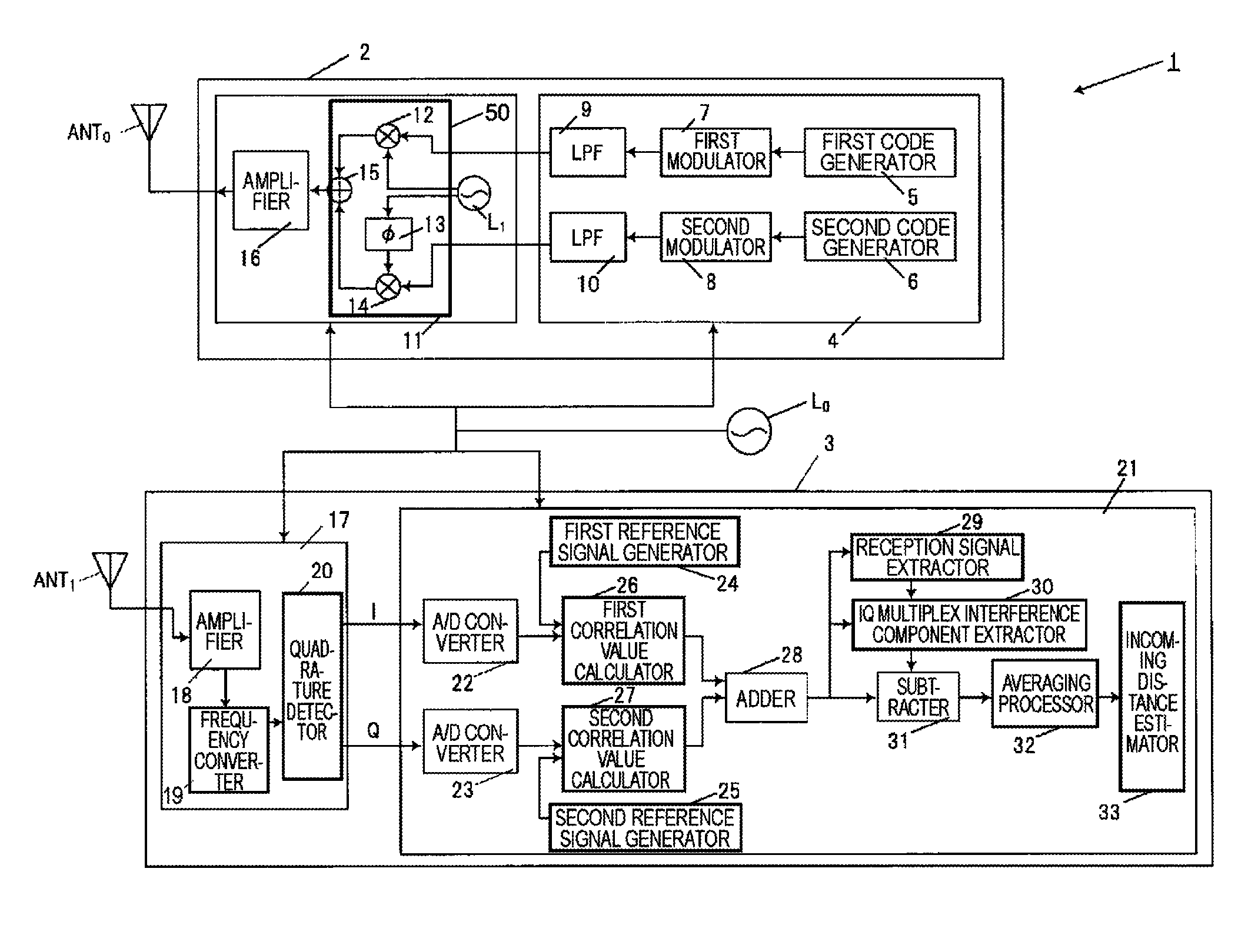
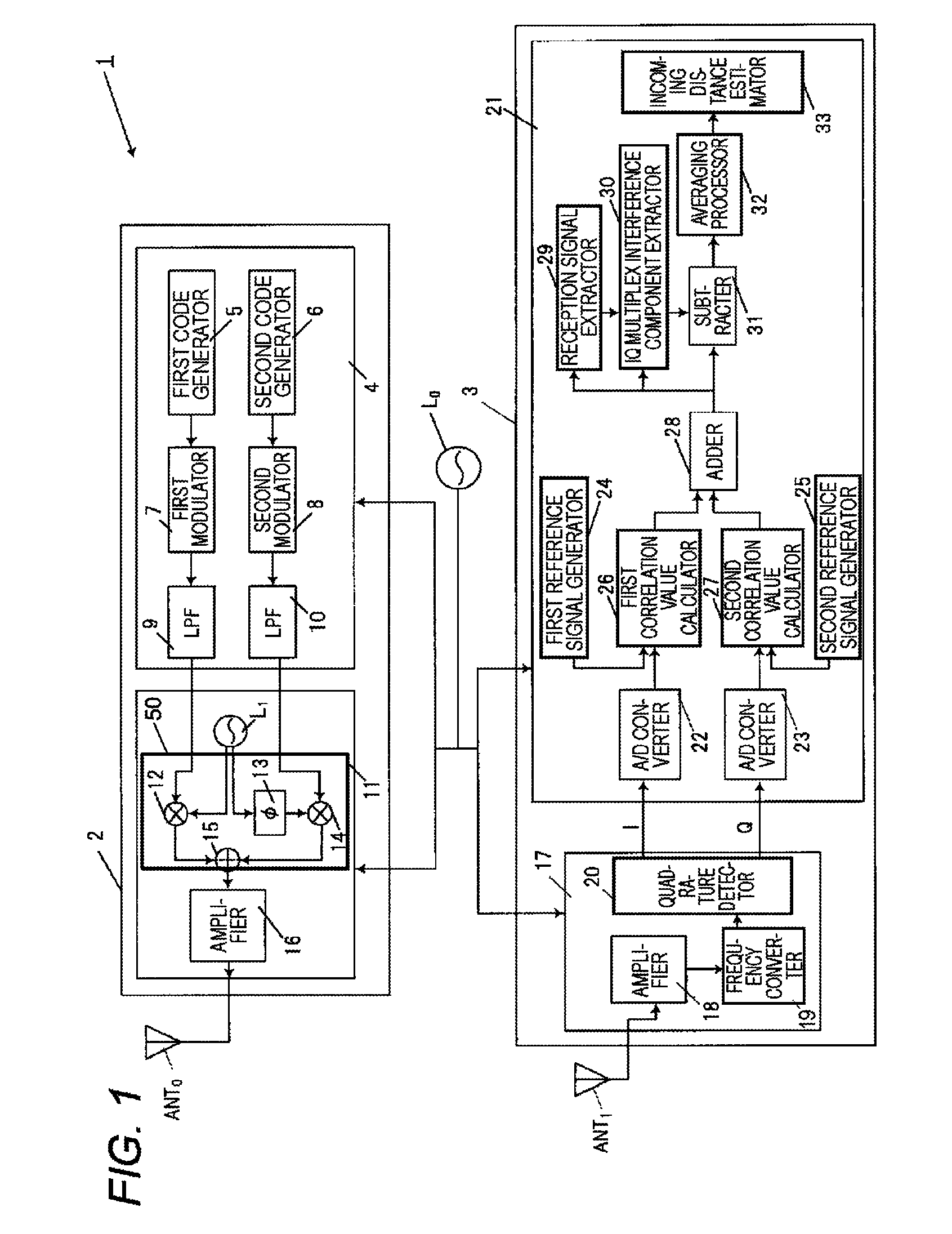
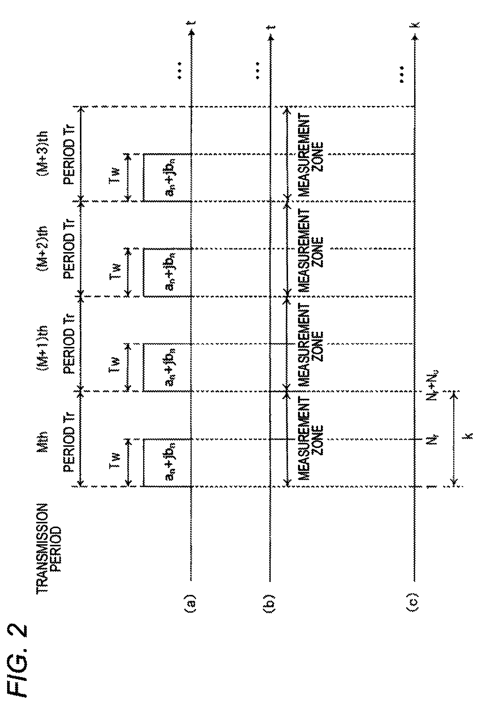
[0047]The configuration and operation of a radar device 1 of a first embodiment will be described with reference to FIGS. 1 to 4. FIG. 1 is a block diagram showing the internal configuration of the radar device 1 of the first embodiment. FIG. 2 shows timing charts related to the operation of the radar device 1 of the first embodiment, (a) of the figure is a view illustrating transmission periods Tr and transmission codes used in the transmission periods Tr, (b) of the figure is a view illustrating measurement zones, and (c) of the figure is a view illustrating relationships between the transmission periods Tr and a discrete time k.

[0048]FIG. 3 is a constellation diagram of a radio frequency transmission signal which is IQ multiplexed in the radar device 1 of the first embodiment. FIG. 4 shows views showing an IQ correlation value AC(k) on an IQ plane, (a) of the figure is a view showing an IQ correlation value AC(k) before an subtraction process by a subtracter 31, (b) of the figure...

second embodiment

[0109]Next, the configuration and operation of a radar device 1a of a second embodiment will be described with reference to FIGS. 5 to 8.

[0110]FIG. 5 is a block diagram showing the internal configuration of the radar device 1a of the second embodiment.

[0111]FIG. 6 shows timing charts related to the operation of the radar device 1a of the second embodiment, (a) of the figure is a view illustrating transmission periods Tr and transmission codes used in the transmission periods Tr, (b) of the figure is a view illustrating measurement zones, and (c) of the figure is a view illustrating relationships between the transmission periods Tr and a discrete time k.

[0112]FIG. 7 shows constellation diagrams of transmission signals in the radar device 1a of the second embodiment, (a) of the figure is a constellation diagram of transmission signals which are IQ multiplexed while an complementary code an is allocated to the I axis, and an complementary code bn is allocated to the Q axis, and (b) of ...


PUM


Abstract

A radio frequency transmission signal is transmitted from a transmission antenna with a predetermined transmission period, and a signal of a reflected wave reflected from a target is received by a reception antenna. A code generator generates a first code sequence and second code sequence that constitute a pair of complementary codes. A first modulator modulates the first code sequence to generate a first transmission signal. A second modulator modulates the second code sequence to generate a second transmission signal. A quadrature modulator performs quadrature modulation by using the generated first and second transmission signals. The radio frequency transmission signal is generated from a signal that is quadrature modulated, and transmitted from the transmission antenna.

Description

BACKGROUND[0001]1. Technical Field[0002]The present invention relates to a radar device which receives a signal of a reflected wave that is reflected from a target, through an antenna to detect the target.[0003]2. Description of the Related Art[0004]A radar device radiates a radio wave from a measuring point, which receives a signal of a reflected wave that is reflected from a target, and which measures the distance between the measuring point and the target, the direction, and the like. Recently, particularly, a radar device which can detect not only an automobile, but also a pedestrian as a target by a high-resolution measurement using a short-wavelength radio wave such as a microwave or a millimeter wave has been developed.[0005]A radar device sometimes receives a signal in which a reflected wave from a target at a short distance and that from a target at a long distance are mixed with each other. In the case where a range side lobe appears in the autocorrelation characteristics ...

Claims


Application Information

Patent Timeline
Patent Type & Authority Patents(United States)
IPC IPC(8): G01S13/10G01S7/282G01S13/28G01S13/58G01S13/00G01S7/00G01S13/93G01S7/288G01S13/931
CPCG01S13/284G01S7/282G01S13/288G01S13/582G01S13/931G01S2007/2886G01S7/2886
Inventor KISHIGAMI, TAKAAKINAKAGAWA, YOICHIMUKAI, HIROHITO
Owner PANASONIC INTELLECTUAL PROPERTY MANAGEMENT CO LTD
Why Eureka
Try Eureka