
Fixture for electronic device

Active Publication Date: 2015-12-15
INVENTEC PUDONG TECH CORPOARTION +1
View PDF5 Cites 5 Cited by
  • Summary
  • Abstract
  • Description
  • Claims
  • Application Information

AI Technical Summary

Benefits of technology

The present invention is about a fixture that can hold multiple electronic devices and easily disassemble them. The fixture includes a first frame and a second frame, which is used to secure a motherboard with a central processing unit and a connection port. The fixture allows for easy assembly and disassembly of electronic devices, making it easier to fix and replace them.

Problems solved by technology

However, because these electronic devices are quite precise, it is not adequate to move the electronic device frequently.

Method used


Image

  • Fixture for electronic device
  • Fixture for electronic device
  • Fixture for electronic device

Examples


Embodiment Construction

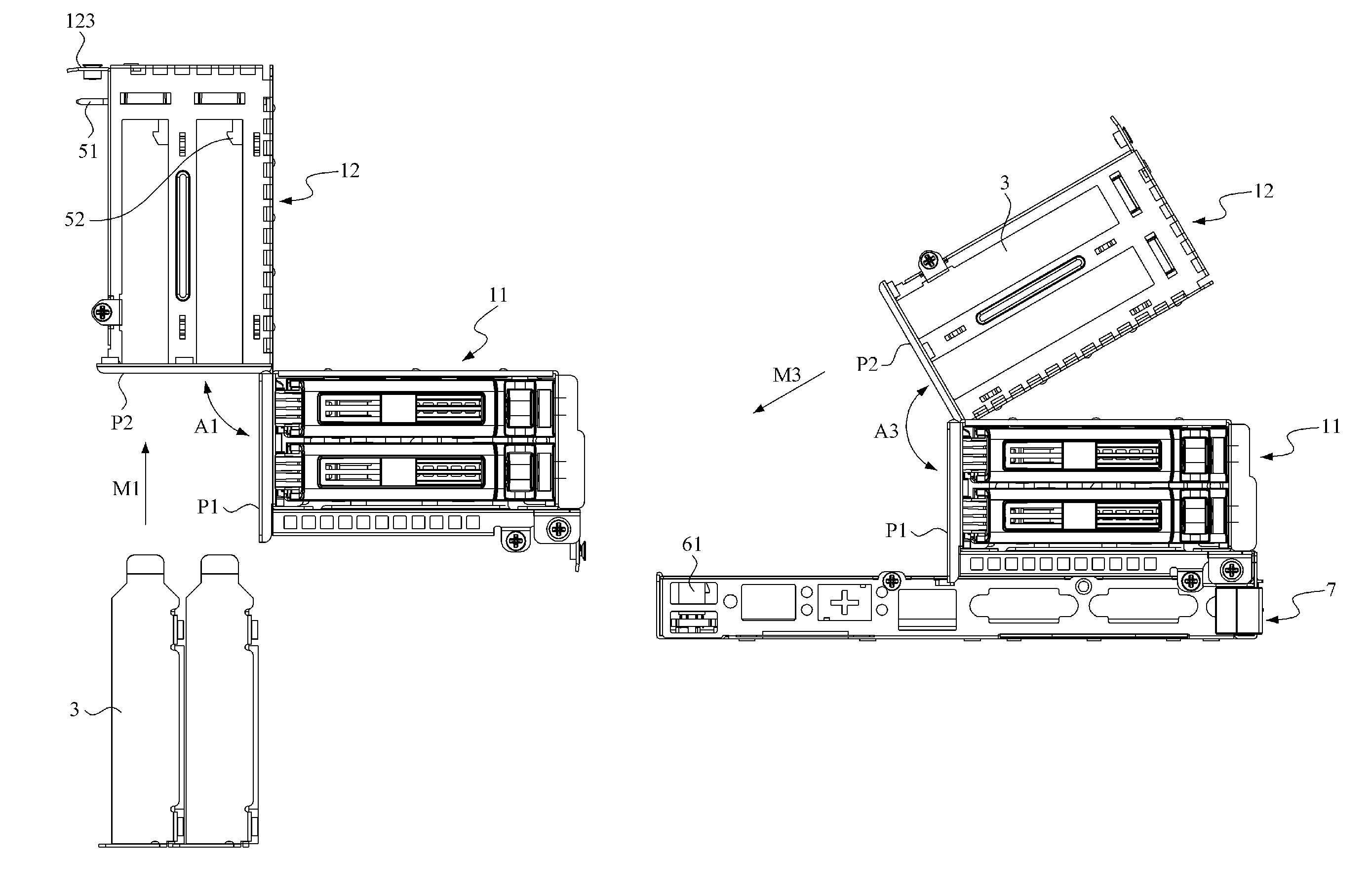
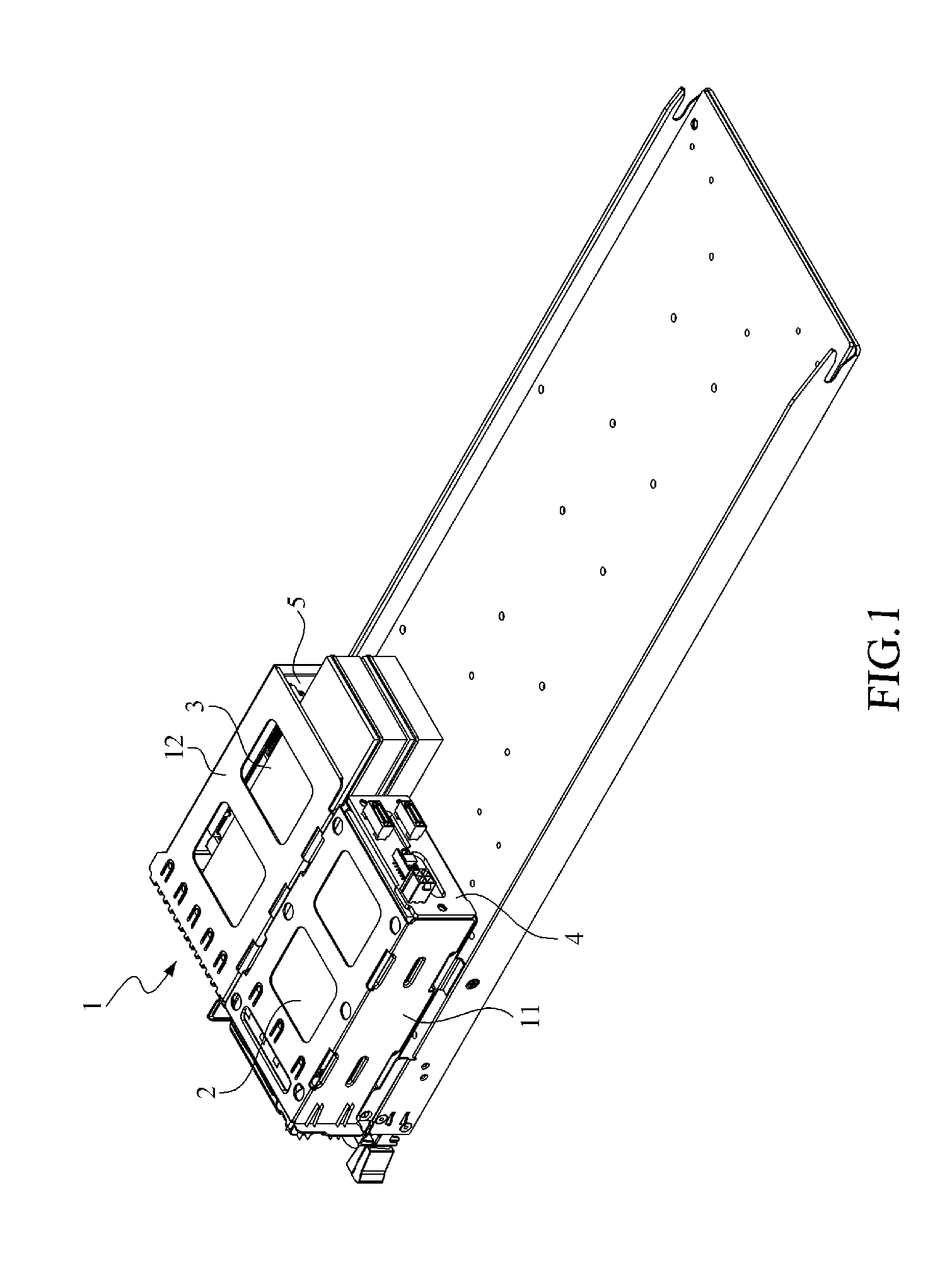
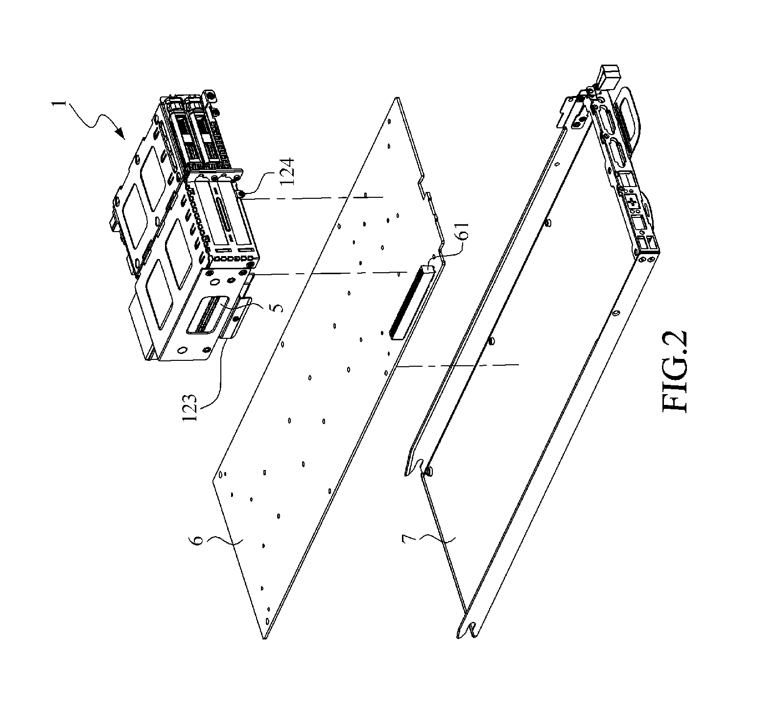
[0025]Please refer to FIG. 1 and FIG. 2, wherein FIG. 1 is a 3D schematic view showing the fixture for electronic device provided in accordance with a preferred embodiment of the present invention being fixed to a tray, and FIG. 2 is a 3D explosive view showing the fixture for electronic device in accordance with a preferred embodiment of the present invention, a motherboard, and the tray. As shown, the fixture 1 for electronic device, which is utilized to fix two first electronic devices 2, two second electronic devices 3, a backplane 4, and a transfer board 5 on a motherboard 6, wherein the motherboard 6 is disposed on a tray 7, and the motherboard 6 includes at least a central processing unit (not shown) and a connection port 61.

[0026]Please further refer to FIG. 3, which is a 3D explosive view showing the fixture for electronic device in accordance with a preferred embodiment of the present invention. As shown, the fixture 1 for electronic device includes a first frame 11, a sec...


PUM


Abstract

A fixture for electronic device includes a first frame and a second frame. The first frame is fixed to a tray. A backplane is disposed on the first frame. A first electronic device is connected to the backplane and set in the first frame. The backplane is electrically connected the first electronic device and a motherboard by a cable, in which the motherboard is arranged on the tray. The second frame is pivotally connected to the first frame. A transfer board is fixed to the second frame. A second electronic device is connected to the transfer board, and assembled into the second frame. The second frame is fixed onto the tray, and the transfer board is connected to a connection port of the motherboard when the second frame is located in a first position, so as to make the second electronic device electrically connect to the motherboard.

Description

FIELD OF THE INVENTION[0001]This invention is related to a fixture for electronic device, and more particularly related to a fixture for fixing a first electronic device and a second electronic device on a motherboard.BACKGROUND OF THE INVENTION[0002]In recent years, attending with the rapid development in smart handheld devices, people spent more and more time on internet and also generated more and more electronic data each day. Meanwhile, people gradually changed the habit of storing electronic data in the terminal device to storing electronic data to the remote server such that the amount of electronic data would not be restricted by the storing module in the terminal device and the data can be effectively reserved.[0003]As mentioned, because people are gradually used to store data in cloud, hardware providers are looking for servers with higher performance. However, a server is usually integrated with a large number of storing apparatuses in order to provide a huge storing spac...

Claims


Application Information

Patent Timeline
IPC IPC(8): H01R13/60H01R12/70
CPCH01R12/7076G06F1/18G06F1/187G11B33/123G11B33/128
Inventor LI, MING-GANGZHAO, XIU-HUA
Owner INVENTEC PUDONG TECH CORPOARTION
Learn More