Fluid pulse generator for cleaning passageways

US9233404B1Inactive Publication Date: 2016-01-12MUNOZ ROBERT J +2
4 Cites 5 Cited by

Patent Information

Authority / Receiving Office
US · United States
Current Assignee / Owner
Publication Date
2016-01-12
Estimated Expiration
Not applicable · inactive patent

Smart Images

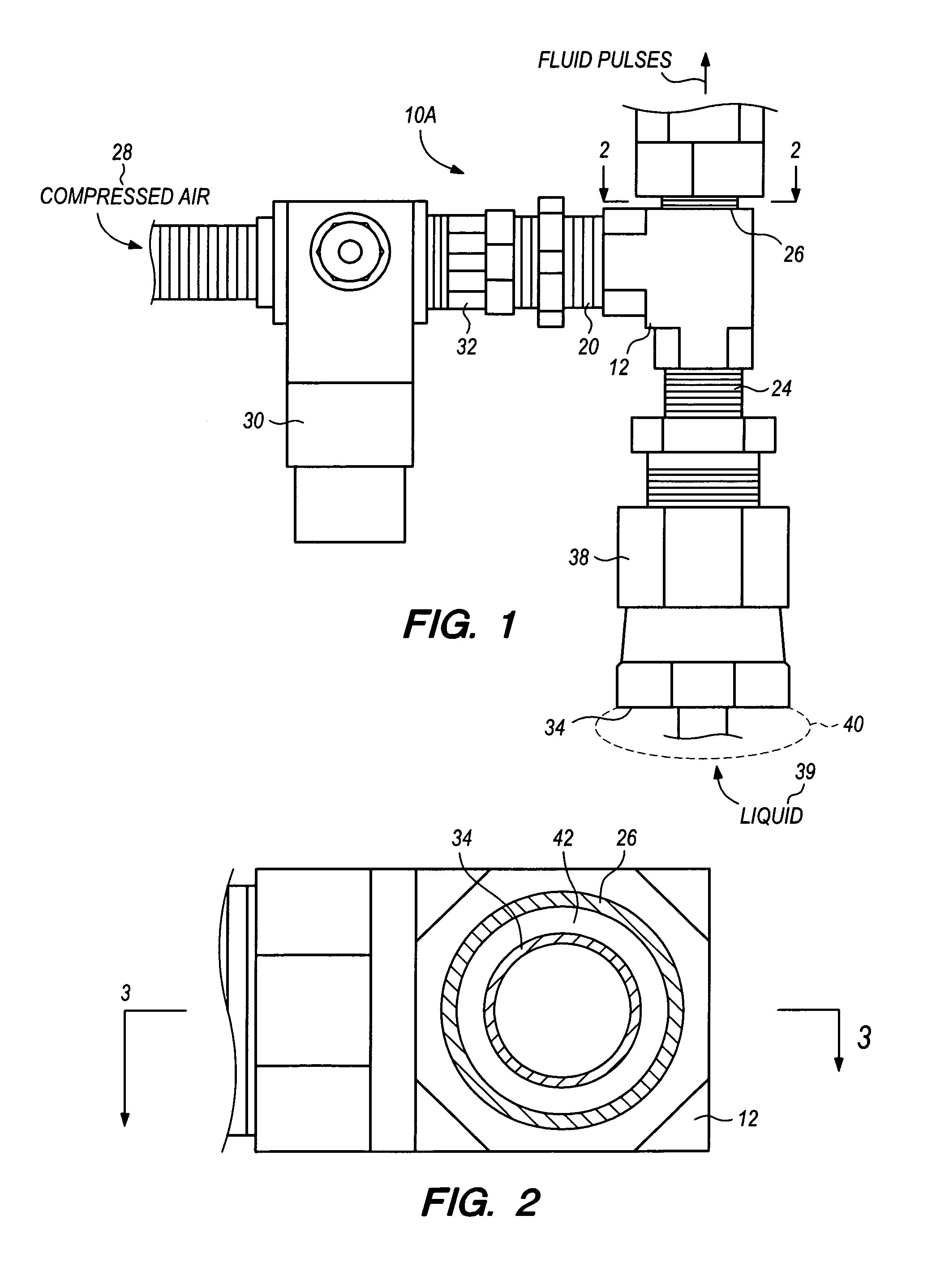
  • Figure 1
    Figure 1
  • Figure 2
    Figure 2
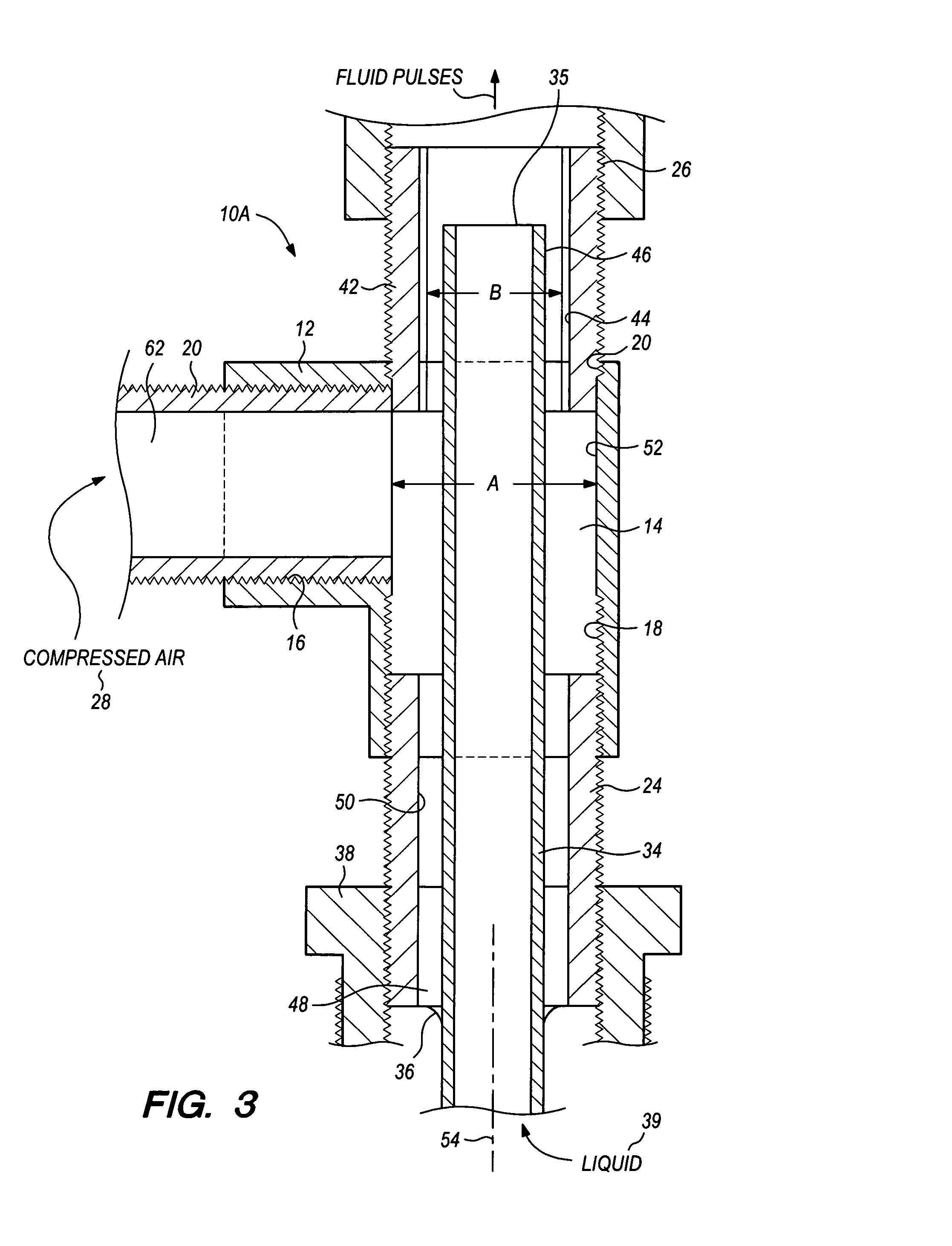
  • Figure 3
    Figure 3
Patent Text Reader

Abstract

The apparatus for producing a pulsing flow of fluids to a fluid line including a housing having first, second and third passages. The first passage communicates with a source of compressed gas and a first conduit, communicating with a solvent liquid source, and passes through the housing. A narrowed transverse dimension between the conduit and the inner chamber of the housing creates a pulsing delivery of fluids from the gas and liquid sources.
Need to check novelty before this filing date? Find Prior Art

Description

BACKGROUND OF THE INVENTION

[0001] The present invention relates to a novel and useful apparatus for producing a pulsing flow of fluid to a fluid line from compressed air and liquid sources.

[0002] Heat exchangers include conduits along parallel paths that are widely employed for carrying cooling and heating fluids in the automotive, aviation, and marine systems. For example, such devices may include condensers, automatic transmission air coolers, engine oil air coolers, fuel coolers, heater cores, radiators, and air conditioning evaporators, and the like.

[0003] A problem exists with such heat exchangers in that they become partially or completely clogged and contaminated over time due to deposits of materials from the cooling fluids. The problem of contamination has often been extensive enough to require removal and replacement of heat exchanger equipment.

[0004] In the past, many of the methods for cleaning and unclogging fluid circuits, using strictly chemical means, has proven to be ti...

Examples

Embodiment Construction

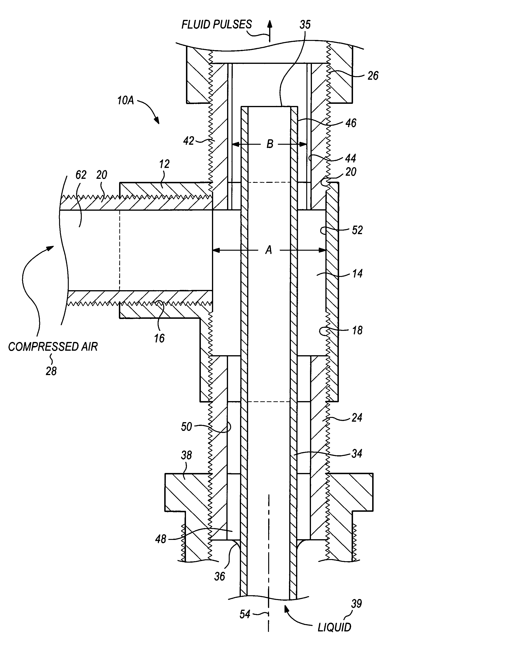
[0028]Various aspects of the present invention will evolve from the following detailed description of the preferred embodiments thereof which should be referenced to the prior described drawings.

[0029]An embodiment of the invention as a whole is shown in the drawings by reference character 10, followed by an upper case letter to denote multiple embodiments.

[0030]The apparatus of the present invention 10A is depicted in FIGS. 1, 2, and 3 and includes as one of its elements a housing 12. Housing 12 includes an inner chamber 14 having a transverse dimension “A”. First passage 16, second passage 18, and third passage 20 lead to inner chamber 14 such that housing 12 is generally tee-shaped. Threaded nipples 22, 24, and 26 threadingly engage first, second, and third passages 16, 18, and 20, respectively.

[0031]With further reference to FIGS. 1, 2, and 3, it may observed that first passage 16 communicates with a source of compressed air or gas 28. Air pressure regulator 30 and check valve 3...