Non-glare reflective LED lighting apparatus with heat sink mounting

a technology of led lighting and heat sink, which is applied in the direction of lighting and heating apparatuses, point-like light sources, semiconductor devices for light sources, etc., can solve the problems of inefficiency of light dispersion, high power consumption, and inconvenient installation, so as to promote efficient heat dissipation, eliminate or reduce glare, and improve the effect of ar

Active Publication Date: 2016-01-12
HUIZHOU LIGHT ENGINE LTD
View PDF55 Cites 0 Cited by
  • Summary
  • Abstract
  • Description
  • Claims
  • Application Information

AI Technical Summary

Benefits of technology

[0007]In light of the above, there exists a need to further improve the art. Specifically, there is a need for an LED lighting apparatus that eliminates or reduces glare, and has an improved, compact thermally-conductive assembly which promotes efficient heat dissipation generated from the LED (such as a high-powered LED) while minimizing obstruction of the light path and the number of components needed in such assembly.

Problems solved by technology

However, such lighting apparatuses present a number of drawbacks.
For example, the popular AR111 halogen apparatus presents the following drawbacks—relatively high power consumption, inefficiency of light dispersion due to the placement of its metal shield in the line sight of the halogen bulb, and its limited effectiveness in preventing glare from the halogen bulb.
These configurations are unable to achieve narrow beam angles, and result in considerable glare since observers are not shielded from the LED light source.
Further, these configurations inefficiently distributes heat; thereby, making the use of high-powered LEDs in these configurations practically prohibitive.

Method used


Image

  • Non-glare reflective LED lighting apparatus with heat sink mounting
  • Non-glare reflective LED lighting apparatus with heat sink mounting
  • Non-glare reflective LED lighting apparatus with heat sink mounting

Examples


Embodiment Construction

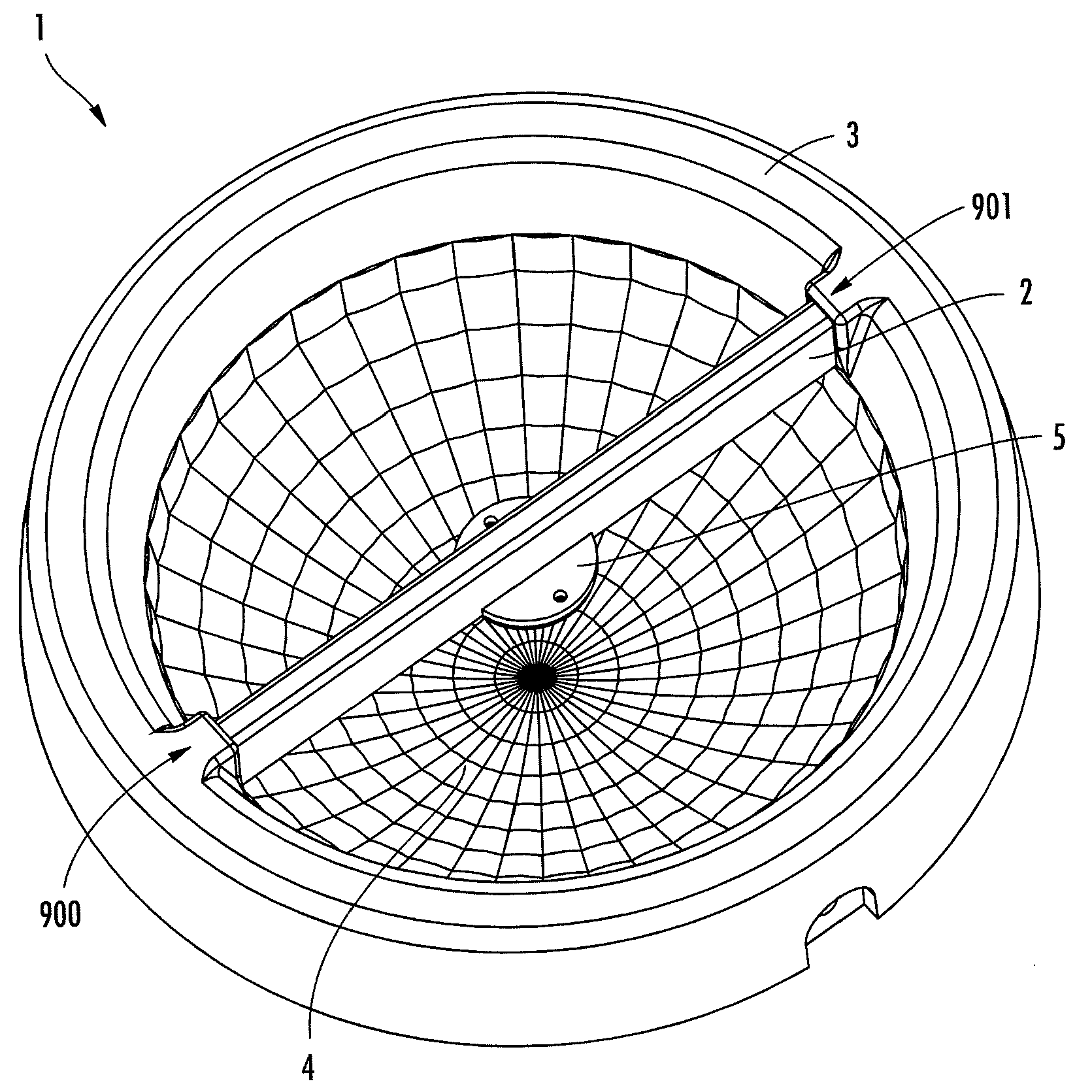
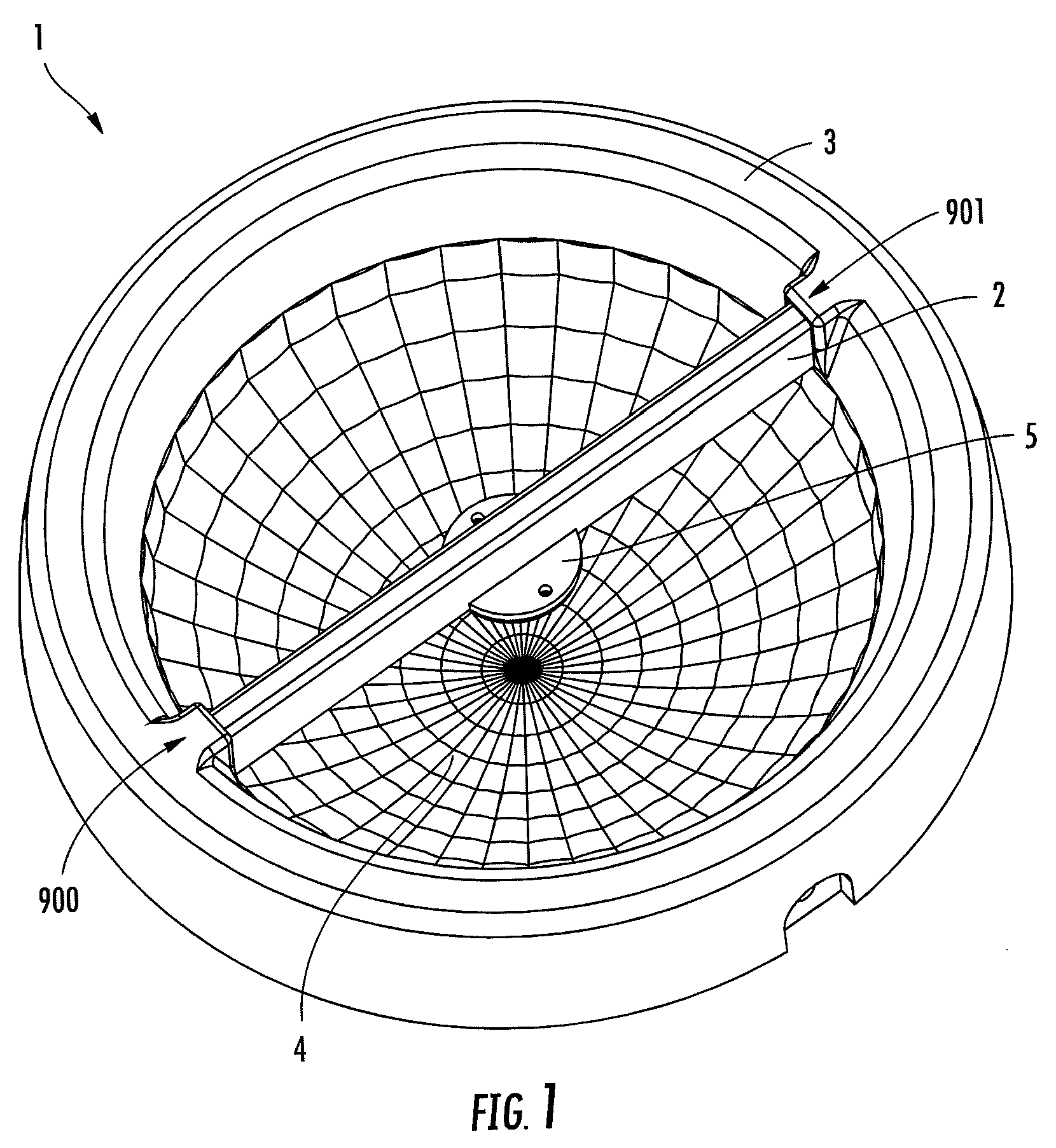
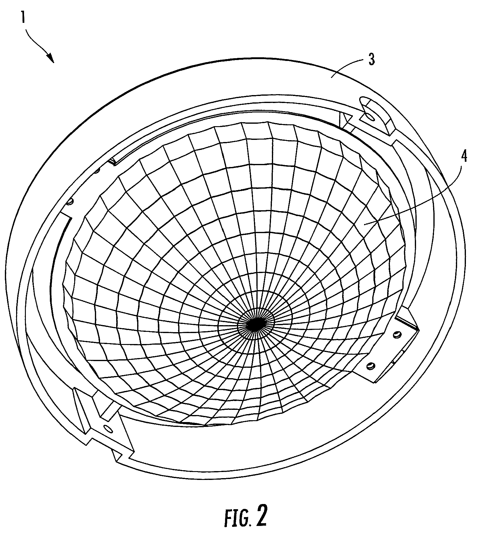
[0056]As shown in FIGS. 1-6, and in accordance with an aspect of the present invention, a lighting apparatus 1 has a reflector 4 which is coupled to a top rim 3, wherein the top rim 3 is coupled to a heat conducting body 2. The heat conducting body 2 contains a heat pipe 8 which is cladded by a cladding 9, and a mounting platform 5 located on one side of the heat conducting body 2 facing opposite the front side of the reflector 4. As shown in FIG. 3, an LED 6 is coupled to a metal core printed circuit board (“PCB”) 7 which is then coupled to the mounting platform 5. The mounting platform 5 is shaped (which, in this aspect of the present invention, is circular) in such a manner that it provides increased non-glare protection from the LED relative to existing lighting apparatuses.

[0057]In this aspect of the present invention, the LED 6 is located above at or near a central optical axis 300 of the reflector 4, and is positioned so that light emitted from the LED 6 is substantially or e...


PUM


Abstract

A lighting apparatus contains a main housing; a reflector disposed within the main housing, and having a front side and a rear side; a heat conducting body comprising at least two heat pipes, wherein a first portion of the at least two heat pipes are parallel to a central axis of the lighting apparatus on the front side of the reflector, and a second portion of each of the at least two heat pipes is in the rear side of the reflector and is thermally coupled to the main housing; a heat conducting head located on the front side of the reflector, and is thermally coupled to the heat conducting body; at least two light-emitting diodes (“LEDs”) thermally coupled to the heat conducting body, and being positioned to face the front side of the reflector so that light emitted from the LEDs are directed to said front side.

Description

CROSS-REFERENCE TO RELATED APPLICATIONS[0001]This is a utility application which is a continuation-in-part of U.S. Ser. No. 12 / 470,332, filed May 21, 2009, which claims priority under 35 U.S.C. §119(e) to U.S. Provisional Patent Application Ser. No. 61 / 055,858, filed May 23, 2008, U.S. Provisional Patent Application Ser. No. 61 / 057,289, filed May 30, 2008, and U.S. Provisional Patent Application Ser. No. 61 / 118,202, filed Nov. 26, 2008, the entirety of which are incorporated herein by reference.[0002]Throughout this application, several patents and references are referenced. Disclosure of these patents and references in their entirety is hereby incorporated by reference into this application.FIELD OF THE INVENTION[0003]The present invention relates to electrical lighting devices and systems and, more specifically, lighting apparatuses using at least one single-chip or multi-chip light-emitting diode (“LED”), back-reflecting collection optics for LEDs, and an improved heat sink mount...

Claims


Application Information

Patent Timeline
Patent Type & Authority Patents(United States)
IPC IPC(8): F21V7/00F21V29/00F21K99/00F21V19/00F21V29/507F21V23/00F21V29/77F21V29/85F21V7/04F21V7/06F21V7/07F21V7/08F21V29/89
CPCF21V7/0008F21K9/137F21V19/0015F21V23/005F21V29/004F21V29/006F21V29/507F21V29/773F21V29/85F21V7/048F21V7/06F21V7/07F21V7/08F21V29/89F21Y2101/02F21K9/233F21Y2115/10F21K9/238F21V29/51F21V7/04
Inventor CHU, TIN POLEUNG, WA HING
Owner HUIZHOU LIGHT ENGINE LTD
Why Eureka
Try Eureka