Filter network arrangement

a filter network and filter technology, applied in repeater circuits, line-transmission details, baseband system details, etc., can solve the problems of signal degradation, increase in complexity and the order of filtering, and large filter size, so as to minimise the variation in gain of filter network arrangement, flatten group delay, and flatten group delay

Inactive Publication Date: 2016-01-12
ASTRIUM GMBH
View PDF1 Cites 0 Cited by
  • Summary
  • Abstract
  • Description
  • Claims
  • Application Information

AI Technical Summary

Benefits of technology

[0014]It has been found that if the one or more external correction networks has substantially the same Q as the filter network, there exist solutions for the one or more correction networks which will flatten the filter passband and also equalise the group delay of the filter network arrangement irrespective of the actual Q. Consequently, the precise Q of the filter network does not need to be known as long as the one or more correction network has substantially the same Q as the filter network, for example if the resonators of the one or more correction networks are of the same type and realised in the same or similar medium as the filter network. In other words, if the Q of the filter and the at least one correction network are the same a solution for the at least one correction network which flattens gain will also flatten group delay. The relationship is not exact so flattening of the gain will not give precise flattening of the group delay. A solution for the one or more correction networks may be selected which gives the best gain flatness, thereby providing a substantially flat group delay as well. In other words, a correction network that minimises the variation in gain of the filter network arrangement can be chosen and, as a consequence, the group delay variation would also be reduced.
[0015]The invention allows a filter network with low Q resonators to be used and the size of the filter network can be reduced compared to filter networks that use high Q resonators to flatten the passband. Since an external network is added, the overall size of the filter network arrangement could of course be double the size of the filter network. However, the overall size would still be smaller or comparable to the filter network in which the passband of the filter was flattened by increasing the Q and, according to the invention, the group delay would also be equalised.
[0017]The order of the or each of the one or more correction network may be the same or lower than the order of the filter network to minimise the size of the network arrangement. Alternatively, the order of the correction network may be greater that the order of the filter network.

Problems solved by technology

Gain and group delay variation as a function of frequency can cause signal degradation.
To obtain a flat passband, very high Q filter resonators are conventionally used, which results in a filter with a relatively large size.
The use of complex zeros or lossy cross couplings to flatten the passband means that an increase in the complexity and the order of the filter is required.

Method used


Image

  • Filter network arrangement
  • Filter network arrangement
  • Filter network arrangement

Examples


Embodiment Construction

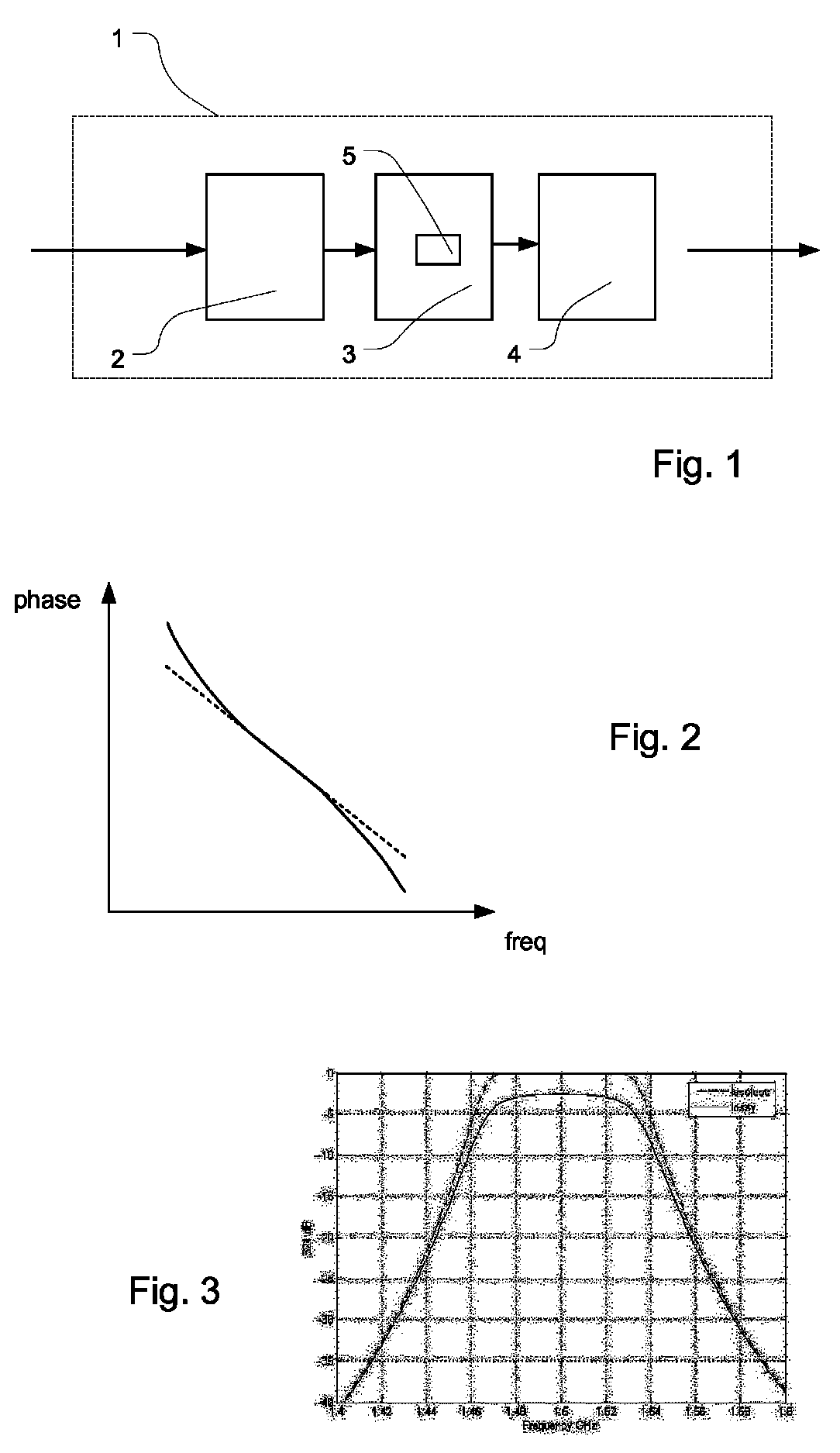
[0042]With reference to FIG. 1, a high-level diagram of a communication system 1 is shown comprising receiver 2 for receiving signals, a signal processing arrangement 3 for processing signals and a transmitter 4 for transmitting signals. The system may be a satellite communication system. The processing arrangement 3 may comprise one or more filter network arrangements 5. The filter network arrangement may, for example, comprise a bandpass filter network and may, for example, be used in a demultiplexer for demultiplexing received signals into a number of frequency channels. Alternatively, the filter network arrangements may be used in an up- or down-converter. It should be realised that a filter network arrangement could alternatively be used for any other suitable purpose.

[0043]The filter network arrangement is configured to let through signals of a specific frequency range and stop signals with frequencies outside the frequency range. The filter network arrangement will have some ...


PUM


Abstract

There is provided a filter network arrangement comprising a filter network; and one or more correction networks, wherein the one or more correction networks is arranged to substantially equalize the passband gain and group delay of the filter network arrangement. Given an appropriate Q for the one or more correction networks, a polynomial for the one or more correction networks can be found that equalizes both the passband gain and group delay and the one or more correction networks can be synthesized from the polynomial.

Description

FIELD OF THE INVENTION[0001]The invention relates to filtering of signals. In particular, the invention relates to the equalising of attenuation and group delay across the passband of a filter network arrangement.BACKGROUND OF THE INVENTION[0002]Communication satellites typically process signals received and transmitted in a number of communication channels. To separate and combine the communication channels, the satellite may make use of a number of filters. Filters involved in signal processing are designed to meet often strict requirements on signal quality. Gain and group delay variation as a function of frequency can cause signal degradation. It is therefore desirable that filters involved in signal processing exhibit close to gain flatness and group delay flatness where possible.[0003]In non-minimum phase filters, cross-couplings within the filters have been used to equalise the group delay of the filters. This technique requires a higher order filter and there is a limit to t...

Claims


Application Information

Patent Timeline
Patent Type & Authority Patents(United States)
IPC IPC(8): H04B3/36H03H21/00H04B7/185H04L25/03
CPCH04L25/03159H03H21/0001H04B7/18513H04L25/03878H04L2025/03375
Inventor YOUNG, DAVID
Owner ASTRIUM GMBH
Why Eureka
Try Eureka