
Protecting device for a user of an aerial lift and aerial lift comprising such a device

a technology for protecting devices and aerial lifts, which is applied in the direction of safety devices for lifting equipment, lifting devices, building scaffolds, etc., can solve the problems of affecting the communication between an operator situated at a height, on the platform of an aerial lift, and one or more other people situated on the ground, and affecting the safety of users

Active Publication Date: 2016-01-19
HAULOTTE GROUP
View PDF21 Cites 11 Cited by
  • Summary
  • Abstract
  • Description
  • Claims
  • Application Information

AI Technical Summary

Benefits of technology

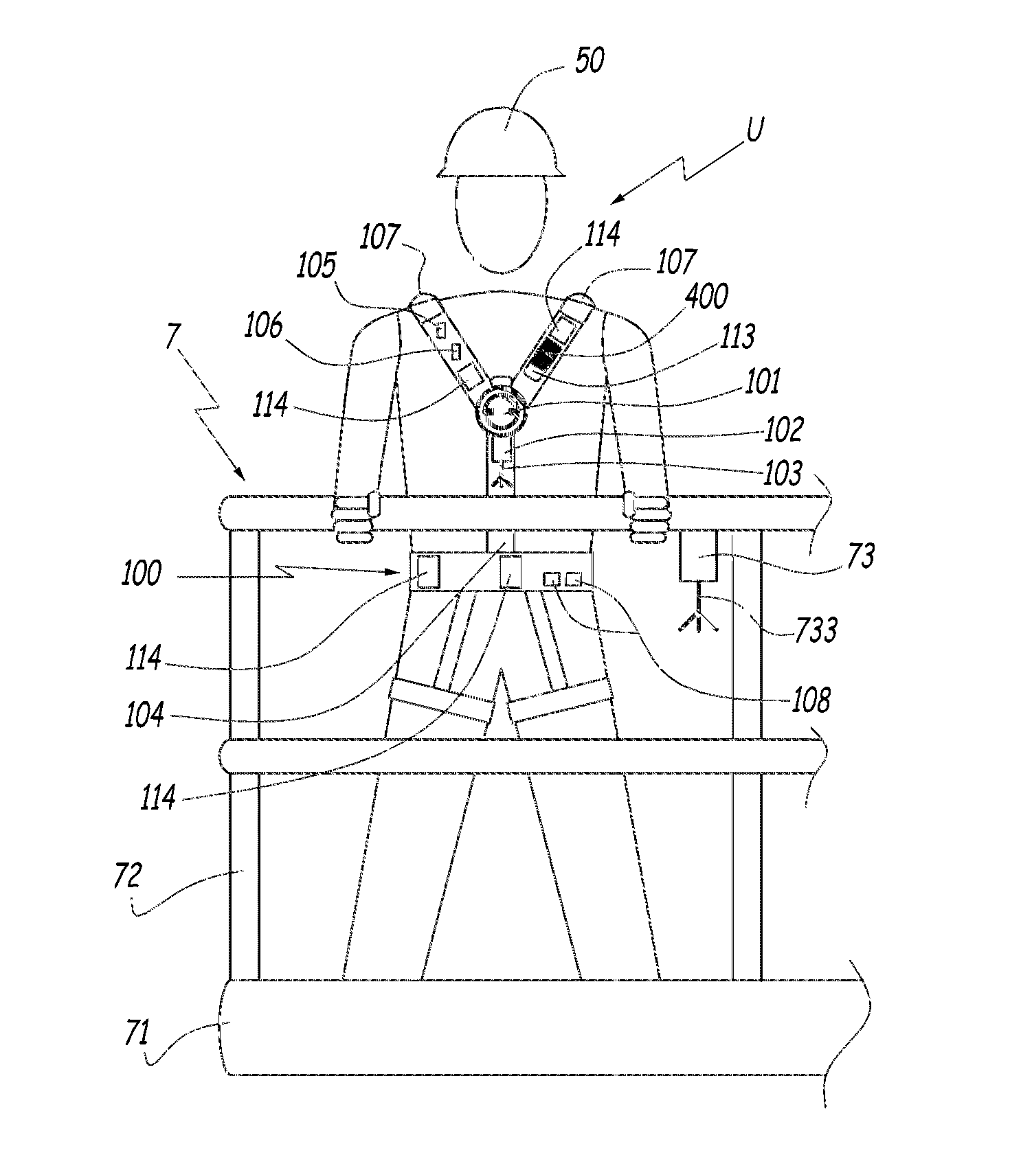
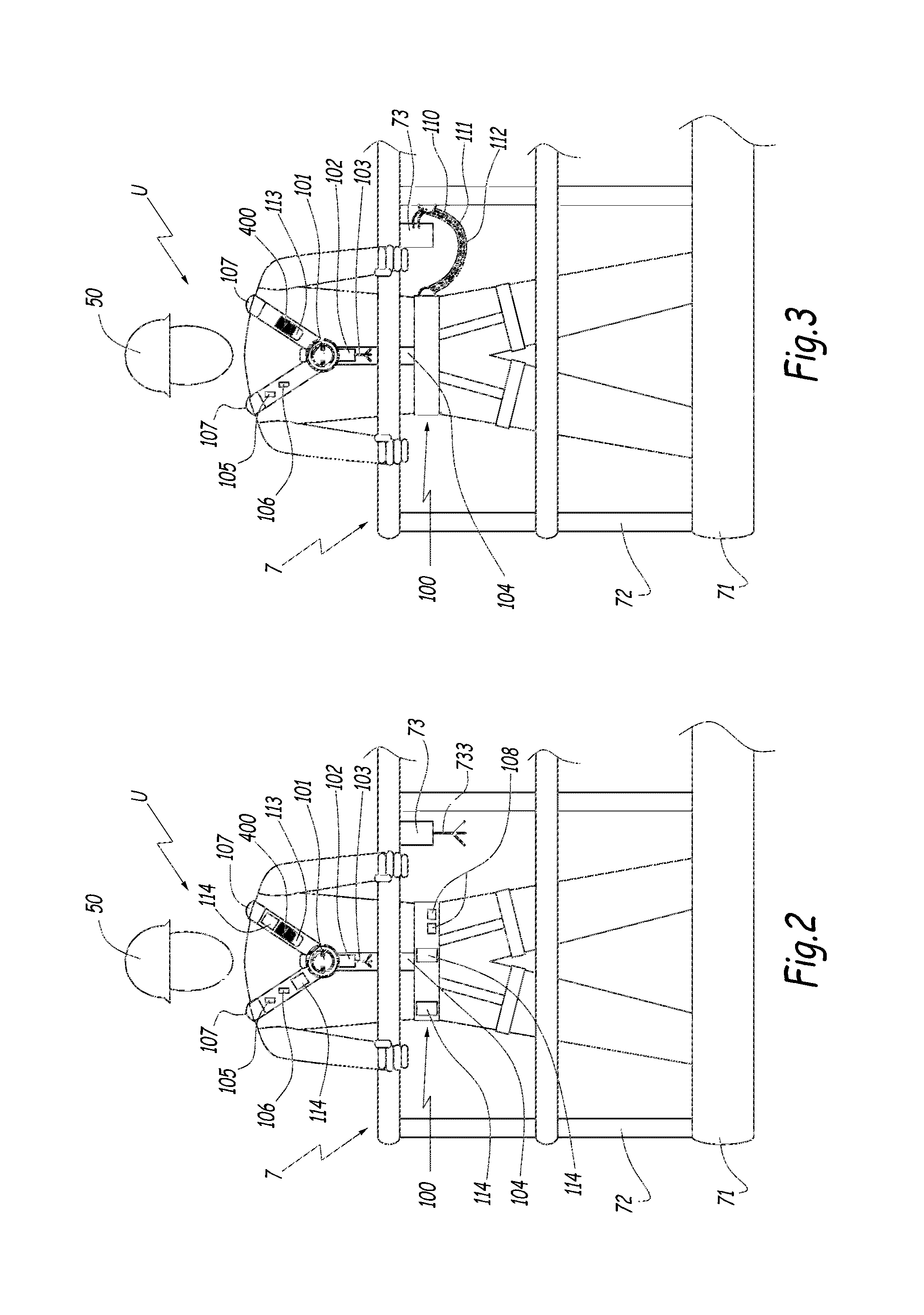
[0009]Owing to the invention, each user may be equipped with a closing element continuously accessible to him, irrespective of his position on the platform, and by which he may give an alert when he detects a dangerous situation, whether it is a situation that concerns him directly or a situation that concerns another person. This is particularly suited to cases where several people are working on a same platform at a height or on adjacent lifts, on a same worksite. The user can actuate the member for triggering an emergency stop through a manual and deliberate action. He can therefore react early when a dangerous situation risks arising.

Problems solved by technology

Furthermore, in case of danger, the communication between an operator situated at a height, on the platform of an aerial lift, and one or more other people situated on the ground is sometimes difficult, due to the distance and the relatively noisy environment that may prevail on the worksite.
Here again, in the event imminent danger, precious seconds may be lost.
Lastly, even in the case of a user using a relatively small lift, said user may find himself stuck on the platform, at a distance from the control console that does not allow him to actuate the emergency stop button, whereas the people on the ground do not immediately notice such a dangerous situation.

Method used


Image

  • Protecting device for a user of an aerial lift and aerial lift comprising such a device
  • Protecting device for a user of an aerial lift and aerial lift comprising such a device
  • Protecting device for a user of an aerial lift and aerial lift comprising such a device

Examples


Embodiment Construction

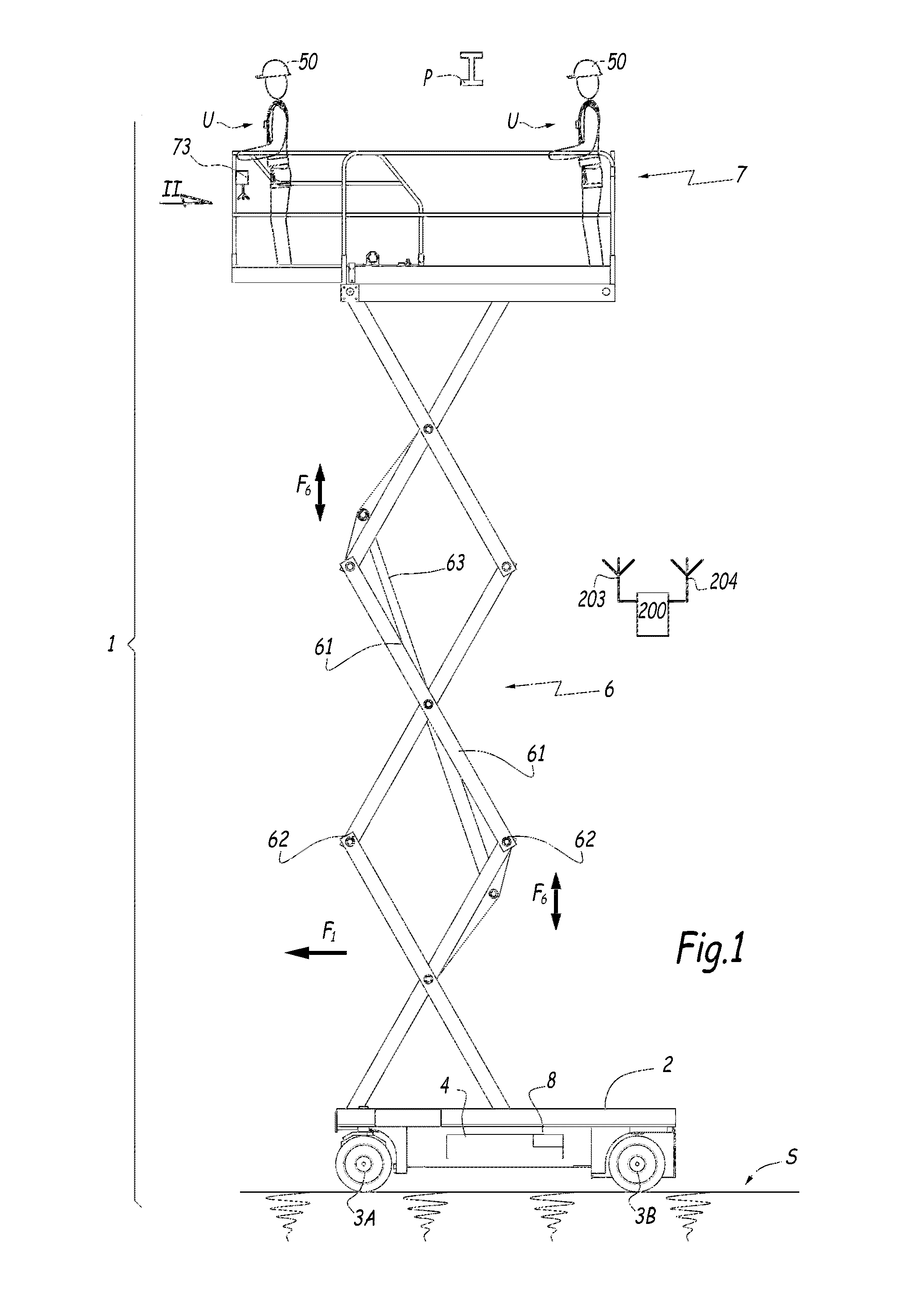
[0030]The lift 1 shown in FIG. 1 is equipped with a chassis 2 resting on the surface of the ground S by means of four wheels, two of which are visible in this figure with references 3A and 3B. The chassis 2 bears a motor assembly 4 with which a structure 6 commonly called a “scissor” structure is associated made up of bars 61 articulated to each other around pivots 62 and commanded by a mechanical device. Alternatively, the scissor structure 6 may be controlled by electric or hydraulic jacks. The possibility of vertical extension of the scissor structure 6 is represented by the double arrow F6. In the upper portion of the scissor structure 6, a platform 7 is provided on which one or more users U, for example two, may be present, as shown in FIG. 1.

[0031]The platform 7 comprises a floor 71 and a railing 72 that define a space in which the user U may stand. The platform 71 is also equipped with a module 73 for controlling the movements of the lift 1 on the surface of the ground S owin...


PUM


Abstract

The device (100) according to the invention for protecting a user (U) of an aerial lift comprises a clothing element (100) designed to be worn by the user (U) and equipped with a signaling mechanism (101-103) connected to a controller (73) of the lift. Said alert means (101-103) comprise a member, such as a button (101) or a pull-tab, designed to be actuated by the user (U) to trigger an emergency stop when the user detects a potentially dangerous situation.

Description

FIELD OF THE INVENTION[0001]The invention relates to a device for protecting a user of an aerial lift as well as an aerial lift comprising, inter alia, such a protective device.BACKGROUND OF THE INVENTION[0002]It is known that a user of an aerial lift must be protected, in particular with respect to risks of impacts with obstacles located near the platform of the lift. To that end, aerial lifts for people generally have an emergency stop button placed on a control console installed on their platform, which makes it possible to react to a potentially dangerous situation. Furthermore, the safety equipment for a user of such a lift may comprise a helmet and / or a harness by which the user is connected to the platform, so as to prevent risks of falling.[0003]A new type of aerial lift is being developed, i.e. so-called large and high-capacity aerial lifts whereof the platforms support several users. These lifts allow several operators to work at heights, in a same area. The various operat...

Claims


Application Information

Patent Timeline
Patent Type & Authority Patents(United States)
IPC IPC(8): B66F17/00A42B3/04A41D1/00B66F11/04
CPCB66F17/006A41D1/002A42B3/046B66F11/04
Inventor LUMINET, PHILIPPELAGOUTTE, CHARLESBEJI, SLAHEDDINE
Owner HAULOTTE GROUP
Learn More