
Systems and methods for remote monitoring, security, diagnostics, and prognostics

a technology of remote monitoring and diagnostics, applied in the field of systems and methods for remote monitoring, security, diagnostics, and prognostics, can solve problems such as physical systems being subject to wear and tear or other damage, information systems being subject to cyber attacks, and cyber threats being particularly difficult to address

Active Publication Date: 2016-01-26
GENERAL ELECTRIC CO
View PDF11 Cites 25 Cited by
  • Summary
  • Abstract
  • Description
  • Claims
  • Application Information

AI Technical Summary

Problems solved by technology

The physical systems may be subject to wear and tear or other damage, while the information systems may be subject to cyber attack, such as from viruses or other malware.
For tactical platforms or critical infrastructure, cyber threats may be particularly difficult to address due to the mission critical and time sensitive nature of such platforms or infrastructure.
Damage to, compromise of, or loss of use of such resources provides disproportionate harm.
Conventional techniques often fail to detect complex cyber threats, and / or lack flexibility to be useful in a variety of contexts.
As one example, conventional techniques may fail to detect a cyber threat that mimics a physical component or aspect of a system.
The inability of conventional systems to accurately and reliably identify malicious (e.g., due to cyber attack) as well as non-malicious (e.g., due to wear and tear of physical components) leads to increased damage to systems being monitored as well as increased down time of such systems.
The potential for damage from malicious attacks is exacerbated by the increasing use of networking by systems utilizing information systems, for example.

Method used


Image

  • Systems and methods for remote monitoring, security, diagnostics, and prognostics
  • Systems and methods for remote monitoring, security, diagnostics, and prognostics
  • Systems and methods for remote monitoring, security, diagnostics, and prognostics

Examples


Embodiment Construction

[0011]Various embodiments will be better understood when read in conjunction with the appended drawings. To the extent that the figures illustrate diagrams of the functional blocks of various embodiments, the functional blocks are not necessarily indicative of the division between hardware circuitry. Thus, for example, one or more of the functional blocks (e.g., processors, controllers or memories) may be implemented in a single piece of hardware (e.g., a general purpose signal processor or random access memory, hard disk, or the like) or multiple pieces of hardware. Similarly, any programs may be stand-alone programs, may be incorporated as subroutines in an operating system, may be functions in an installed software package, and the like. It should be understood that the various embodiments are not limited to the arrangements and instrumentality shown in the drawings.

[0012]As used herein, the terms “system,”“unit,” or “module” may include a hardware and / or software system that ope...


PUM


Abstract

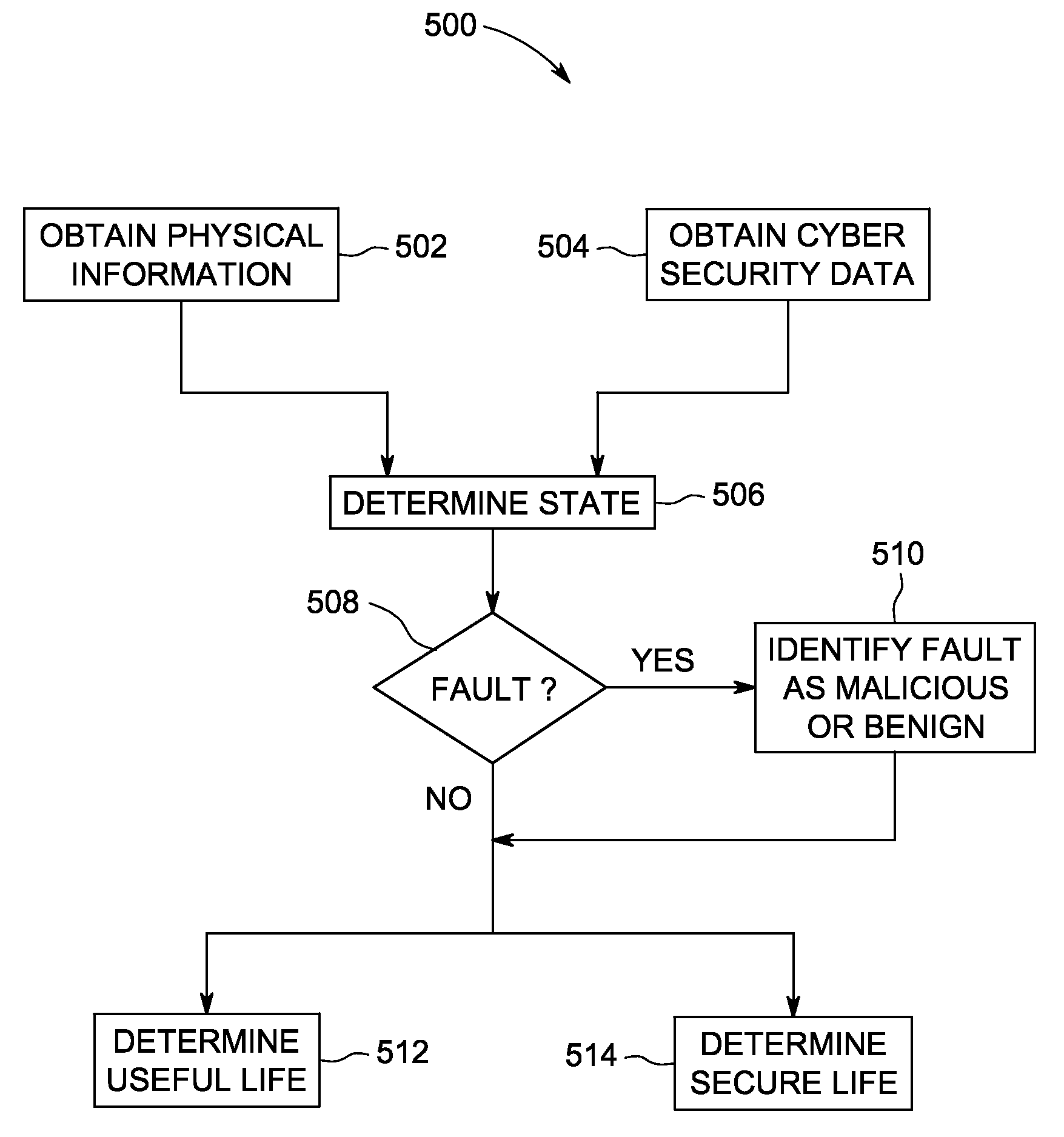
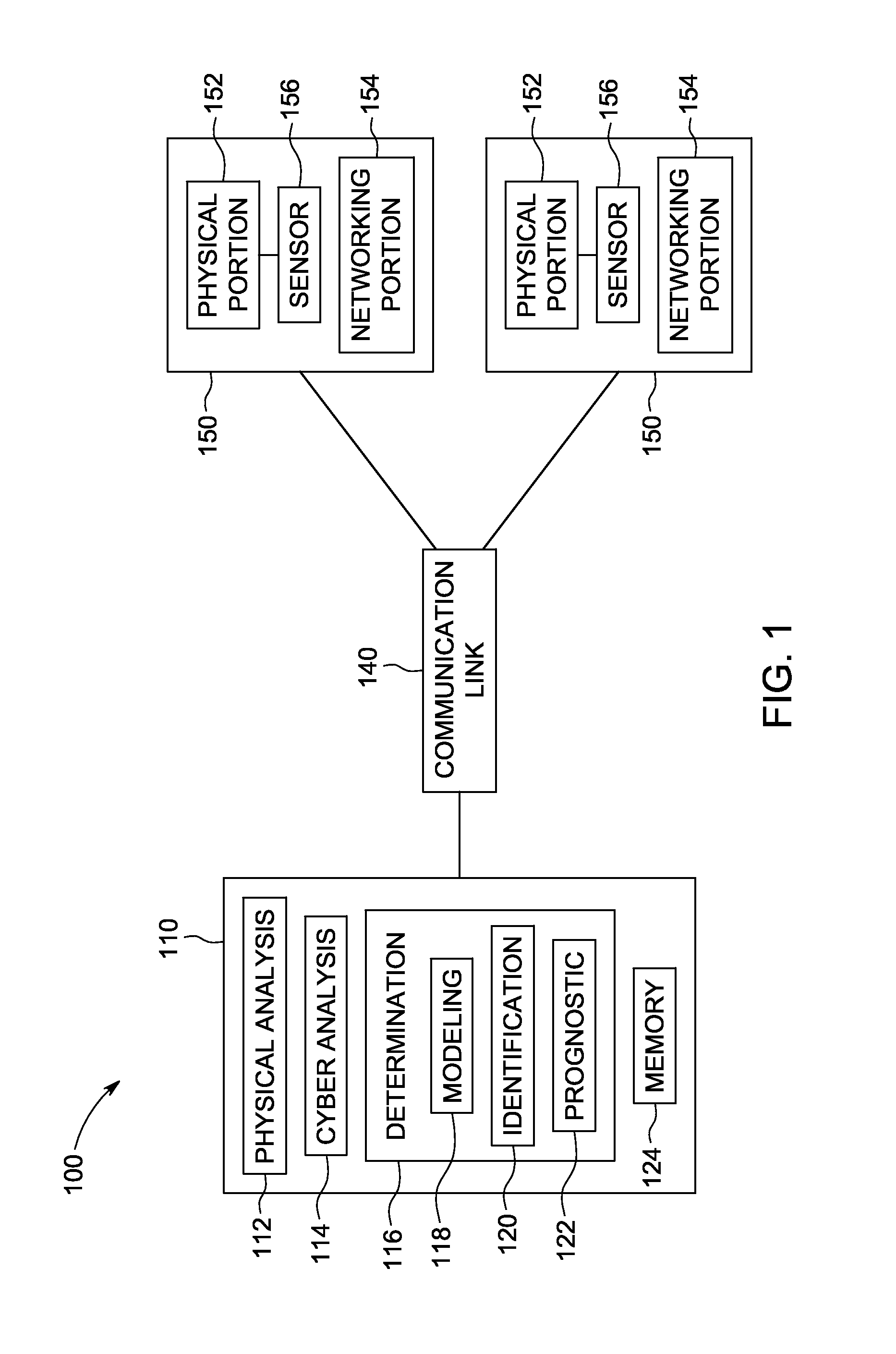
A system includes a physical analysis module, a cyber analysis module, and a determination module. The physical analysis module is configured to obtain physical diagnostic information, and to determine physical analysis information using the physical diagnostic information. The cyber analysis module is configured to obtain cyber security data of the functional system, and to determine cyber analysis information using the cyber security data. The determination module is configured to obtain the physical analysis information and the cyber analysis information, and to determine a state of the functional system using the physical analysis information and the cyber analysis information. The state determined corresponds to at least one of physical condition or cyber security threat. The determination module is also configured to identify if the state corresponds to one or more of a non-malicious condition or a malicious condition.

Description

BACKGROUND[0001]Complex systems may utilize both physical components configured to provide work (e.g., energy, movement, or the like) along with networking or information systems that may exchange information with external systems. The physical systems may be subject to wear and tear or other damage, while the information systems may be subject to cyber attack, such as from viruses or other malware.[0002]For tactical platforms or critical infrastructure, cyber threats may be particularly difficult to address due to the mission critical and time sensitive nature of such platforms or infrastructure. Damage to, compromise of, or loss of use of such resources provides disproportionate harm. Conventional techniques often fail to detect complex cyber threats, and / or lack flexibility to be useful in a variety of contexts. As one example, conventional techniques may fail to detect a cyber threat that mimics a physical component or aspect of a system. The inability of conventional systems to...

Claims


Application Information

Patent Timeline
Patent Type & Authority Patents(United States)
IPC IPC(8): G06F21/55
CPCG06F21/55G05B23/024
Inventor EVANS, SCOTT CHARLESARTHUR, RICHARD BROWNELLBOUQATA, BOUCHRAMISHRA, PIYUSHYAN, WEIZHONGVARMA, ANIL
Owner GENERAL ELECTRIC CO
Learn More