Cervical implant with exterior face plate

a cervical implant and face plate technology, applied in the field of cervical implants with exterior face plates, can solve the problems of degeneration of the spine, pain and/or nerve damage, destabilization of the spine, etc., and achieve the effect of low profil

Active Publication Date: 2016-02-02
SPINESMITH PARTNERS
View PDF7 Cites 7 Cited by
  • Summary
  • Abstract
  • Description
  • Claims
  • Application Information

AI Technical Summary

Problems solved by technology

Due to trauma, disease, and / or aging, the spine may be subject to degeneration.
This degeneration may destabilize the spine and cause pain and / or nerve damage.
One problem with prior art spinal fusion techniques relates to device migration.
In examples where bone screws are used, the insertion and tightening of the bone screws tends to cause device migration.
Another problem with typical prior art fusion techniques is that fusion devices, or associated plates or fasteners, protrude excessively from the spine, causing discomfort, damage, or danger to surrounding vascular or neurological tissues.
Yet another problem with the prior art fusion techniques is the difficulty with placing supplemental fixation (i.e.: plates and screws) due to gross anatomy constraints, surgical approach, vasculature and neurologic tissues and structures, and variable bone quality of the vertebrae.

Method used


Image

  • Cervical implant with exterior face plate
  • Cervical implant with exterior face plate
  • Cervical implant with exterior face plate

Examples


Embodiment Construction

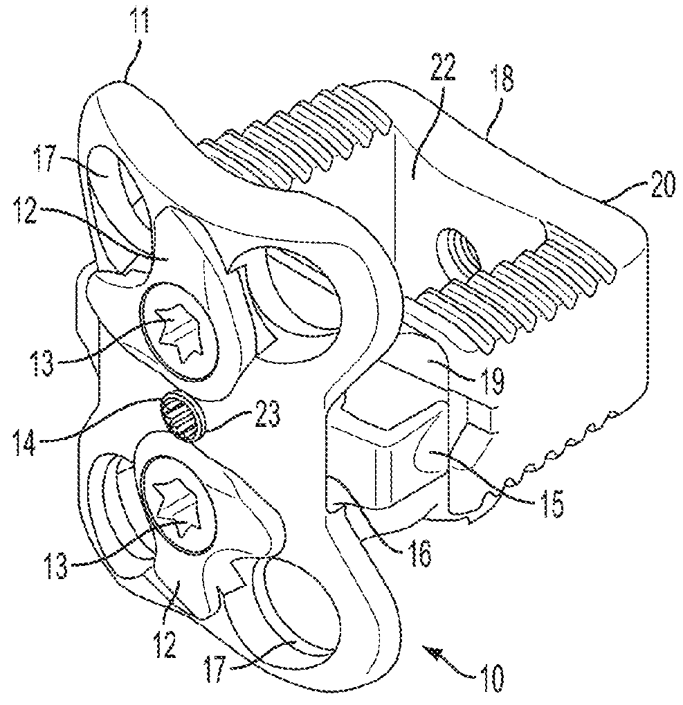
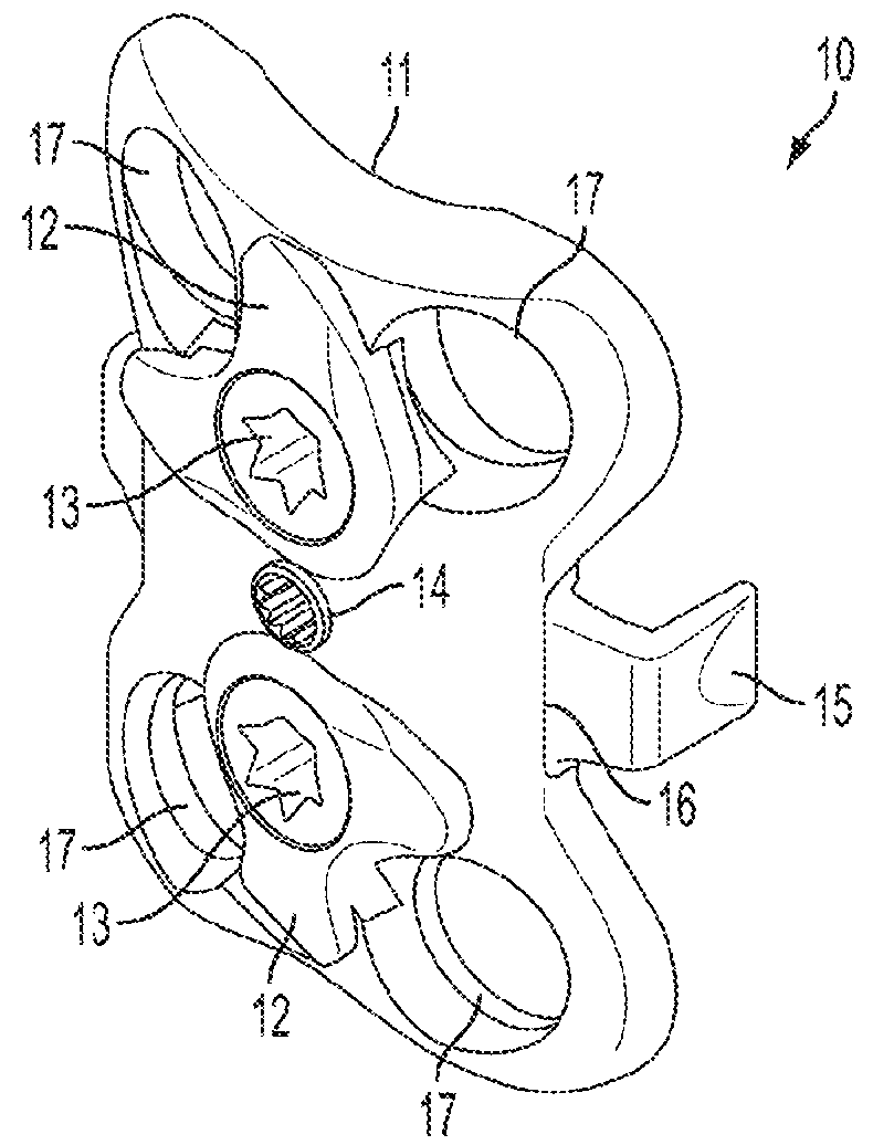
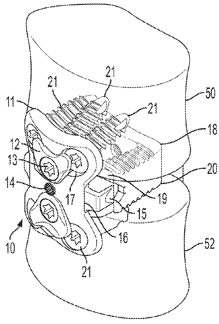
[0011]A typical technique for cervical disk fusion is for the surgeon to build a construct of the following components:

[0012]A spacer / cage, which is used to restore and maintain the appropriate space between vertebral bodies, and to serve as a holder for bone graft material.

[0013]An anterior plate along with several bone screws, which is used to stabilize, immobilize, and provide temporary fixation, until permanent fusion occurs.

[0014]In cases of extreme instability and / or possible trauma, the surgeon will often use posterior fixation, possibly in the form of rods and pedicle screws, to supplement the anterior plate fixation.

[0015]Without actually performing both posterior and anterior fixation, it is desired to create a device and / or method that would achieve equivalent results with only anterior fixation. A secondary problem solved by embodiments of the claimed invention involves the ability to easily position the anterior plate relative to the centerline of the spine and its alig...


PUM


Abstract

The invention is directed to a spinal fusion device, comprising a load bearing component and an anterior component, wherein the load bearing component and the anterior component are configured to mate together by complimentary coupling members, and further comprising an external outer plate configured to span two vertebrae, wherein the outer plate includes bores configured to receive bone screws for coupling to vertebrae.

Description

CROSS-REFERENCES TO RELATED APPLICATIONS[0001]This Application claims the benefit under 35 U.S.C. §119(e) of U.S. Provisional Patent Application No. 61 / 714,376 filed Oct. 16, 2012, which is incorporated herein by reference in its entirety as if fully set forth herein. This Application is a continuation-in-part of application Ser. No. 13 / 135,675 filed Jul. 12, 2011, and is a continuation-in-part of application Ser. No. 13 / 200,911 filed Oct. 4, 2011, and is a continuation-in-part of application Ser. No. 14 / 020,374 filed Sep. 6, 2013, each of which is incorporated herein by reference in its entirety as if fully set forth herein.BACKGROUND OF THE INVENTION[0002]The spine is a series of movable segments made up of vertebrae and discs. Due to trauma, disease, and / or aging, the spine may be subject to degeneration. This degeneration may destabilize the spine and cause pain and / or nerve damage. Medical procedures are often required to either ease back pain, repair damage, or to prevent futu...

Claims


Application Information

Patent Timeline
Patent Type & Authority Patents(United States)
IPC IPC(8): A61F2/44A61B17/80A61B17/70A61F2/30
CPCA61F2/4455A61B17/7059A61B17/8061A61F2/30744A61F2/447A61F2002/30131A61F2002/30168A61F2002/30331A61F2002/30482A61F2002/30489A61F2002/30509A61F2002/30522A61F2002/30561A61F2002/30787A61F2002/30904A61F2002/4475A61F2002/30487A61F2002/30507A61F2002/30593A61B17/8042
Inventor DUNWORTH, KEVINKANA, RICHARD J.ROSSMAN, JOHN B.
Owner SPINESMITH PARTNERS
Why Eureka
Try Eureka