

Methods and devices for notifying and determining patterns of common reference signals
a common reference signal and signal technology, applied in the field of communication, can solve the problems of reducing the experience of edge users, limiting the entire capacity of a system largely, and costing the whole cell throughpu
- Summary
- Abstract
- Description
- Claims
- Application Information
AI Technical Summary
Benefits of technology
Problems solved by technology
Method used
Image

Examples
case 2
[0061]This means that when the CoMP set contains 3 BSs (BS0, BS1 and BS2, wherein BS0 is a main cell) and n is 2, the CoMP transmission schemes can be classified into three cases as follows:[0062]case 1: BS0, BS1 and BS2 transmit the PDSCH to the UE;[0063]case 2: BS1 does not transmit the PDSCH to the UE; and[0064]case 3: BS2 does not transmit the PDSCH to the UE.
[0065]Thus, the solutions for notifying and determining the patterns provided in the disclosure can be used for supporting to notify the UE of CRS configurations of three cells or one cell, respectively. Compared with the existing similar solutions, the solutions of the disclosure have the advantage of more flexibility in the same overheads, or less overheads in the same flexibility.
[0066]It is noted that the correspondences between the bits and the transmission schemes are not limited to the cases shown in the Table and may be modified depending on the actual demands.
[0067]Thus, when the transmission set contains more than...
embodiment i
[0074] (Support to Notify the UE of CRS Patterns of Three Cells)
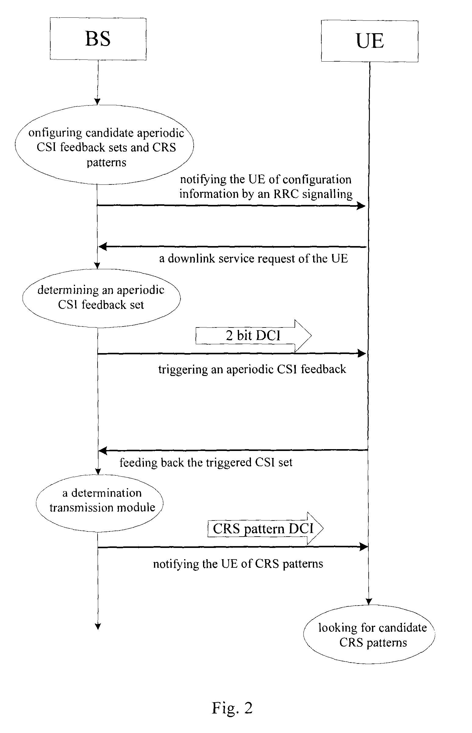
[0075]The following description will be made by taking TR36.819 CoMP scenario 2 for example. Refer to FIG. 3, a CoMP measurement set contains 3 BSs (BS0, BS1 and BS2, wherein BS0 is a main cell and the remaining cells are coordinated cells), n is 2, BS0 is eNB, BS1 and BS2 are high Tx power RRHs, and the connection among the BSs is achieved by fibers or other manners. FIG. 3 illustrates a flow chart of triggering the aperiodic CSO feedbacks and looking for CRS pattern configurations. The steps to be implemented are as follows:
case 1
[0076]Step 1: classifying all the possible CoMP transmission schemes into the following cases based on whether the CoMP transmission points transmit the PDSCHs to the UE:[0077]case 1: BS1 and BS2 transmit the PDSCH to the current UE;[0078]case 2: BS1 does not transmit the PDSCH to the current UE; and[0079]case 3: BS2 does not transmit the PDSCH to the current UE.
[0080]Wherein, in case 1, BS0, BS1 and BS2 transmit the PDSCHs to the UE, or BS1 and BS2 transmits the PDSCHs to the current UE. Because BS0 is the main cell of the current UE, the possibility (BS1 and BS2 transmit the PDSCH to the current UE) is very low. The three CoMP transmission schemes may be further simplified as follows:[0081]case 1: BS0, BS1 and BS2 transmit the PDSCH to the UE;[0082]case 2: BS1 doesn't transmit the PDSCH to the UE; and[0083]case 3: BS2 doesn't transmit the PDSCH to the UE.
[0084]Step 2: configuring aperiodic CSI feedbacks in accordance with the different transmission schemes based on the conclusions...
PUM
 Abstract
Description
Claims
Application Information