
Structural lining system

a technology of structural lining and lining elements, which is applied in the direction of artificial water canals, construction, agriculture, etc., can solve the problems of water, cost, labor, and insufficient repair and maintenance of unlined ditches, and achieve the effect of minimizing the manipulation of liner elements

Active Publication Date: 2016-03-29
AMERICAN LEAK DETECTION IRRIGATION INC
View PDF87 Cites 3 Cited by
  • Summary
  • Abstract
  • Description
  • Claims
  • Application Information

AI Technical Summary

Benefits of technology

[0019]Connections of the straight formed sections now incorporate a tight tolerance male / female connection that eliminates the need for a collapsible foam or rubber gasket to ensure a water tight connection. These tight tolerance male / female connections can also be incorporated into fan shaped elbow sections, as discussed above. With this novel injection molding process, fewer parts are required for installation, and manipulation of the liner elements is minimized.
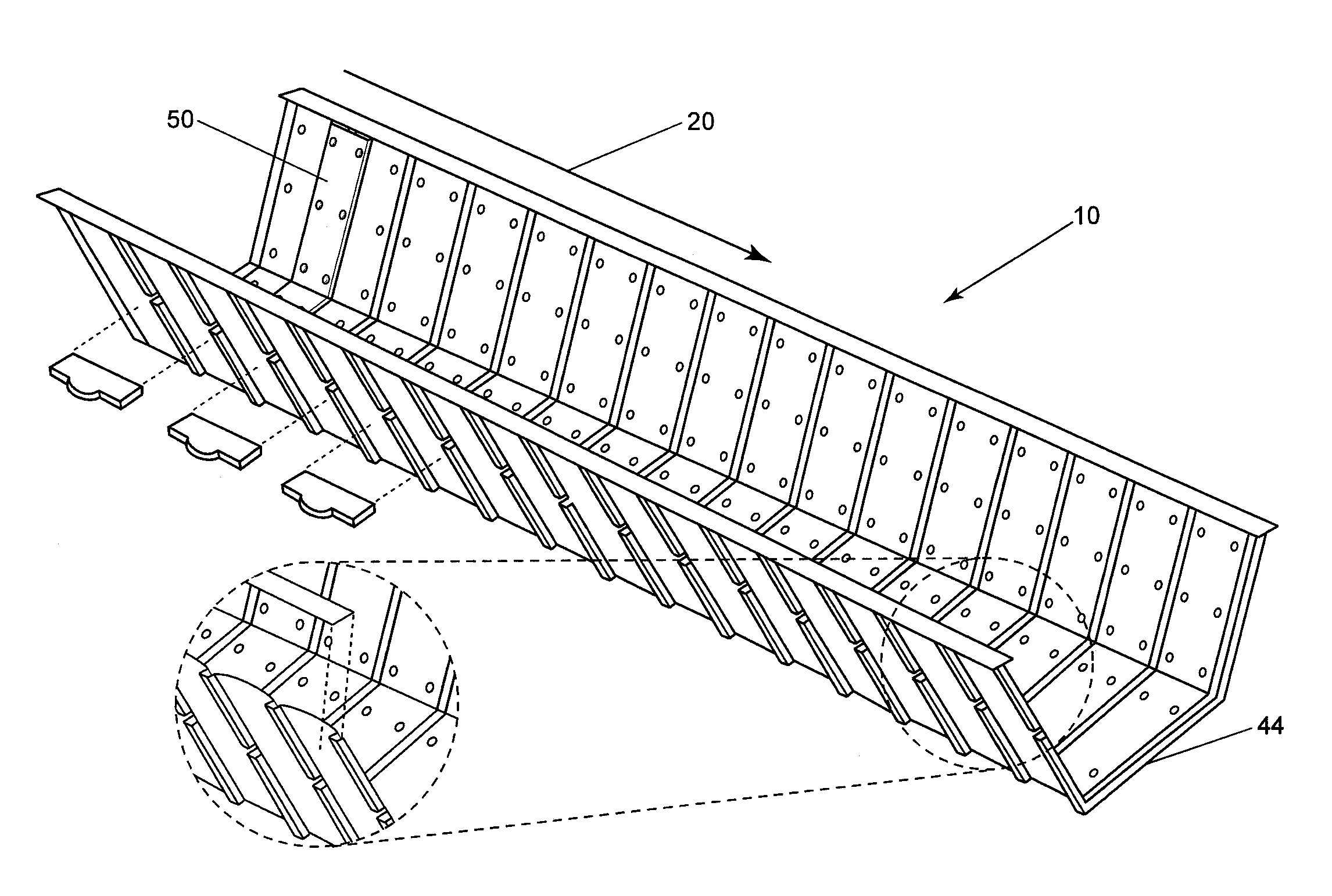
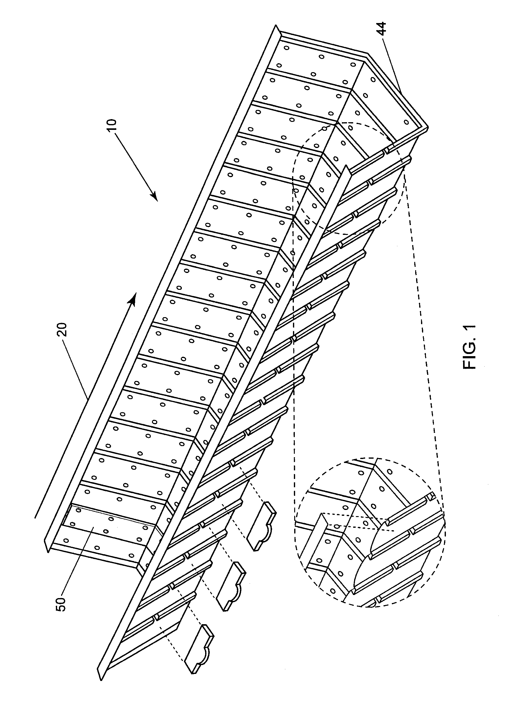
[0020]A new feature in the new design is the ability to provide an anchoring tab that can be inserted at the bottom of the trapezoidal section on either side in the slots provided. The purpose is to provide a self-securing feature that will anchor the liner in place with the use of backfill earthen material. In this manner, the weight of the backfill material will fill in the volume / space between the inverted channels on the insert tab securing the liner in place.

Problems solved by technology

During transportation of water through earthen ditches that are unlined by a material other than dirt (“unlined ditches”), significant quantities of that ever more precious commodity, water, are lost because of seepage, erosion, trans-evaporation, and other causes.
Because repair and maintenance of unlined ditches is costly and labor intensive, various methods for lining unlined ditches have been suggested.
Those suggestions; however, have proven inadequate for a number of reasons including at least cost and unresponsiveness to modern environmental concerns.
Some materials, like concrete, are difficult to install in remote geographical areas, are inflexibly positioned once installed, and often require major construction efforts that are neither practical nor affordable based on cost-benefit analyses.
Also, given the characteristics of the thermos-forming process, the draw depth of the tool yielded parts that were inconsistent in wall thickness leaving the corrugations thin and inconsistent in the valleys, rendering the overall part venerable to puncturing given live loading situations such as animals walking in the channel, installation in hot temperatures, and brittleness in cold temperatures.

Method used


Image

  • Structural lining system
  • Structural lining system
  • Structural lining system

Examples


Embodiment Construction

Best Modes for Carrying Out the Invention

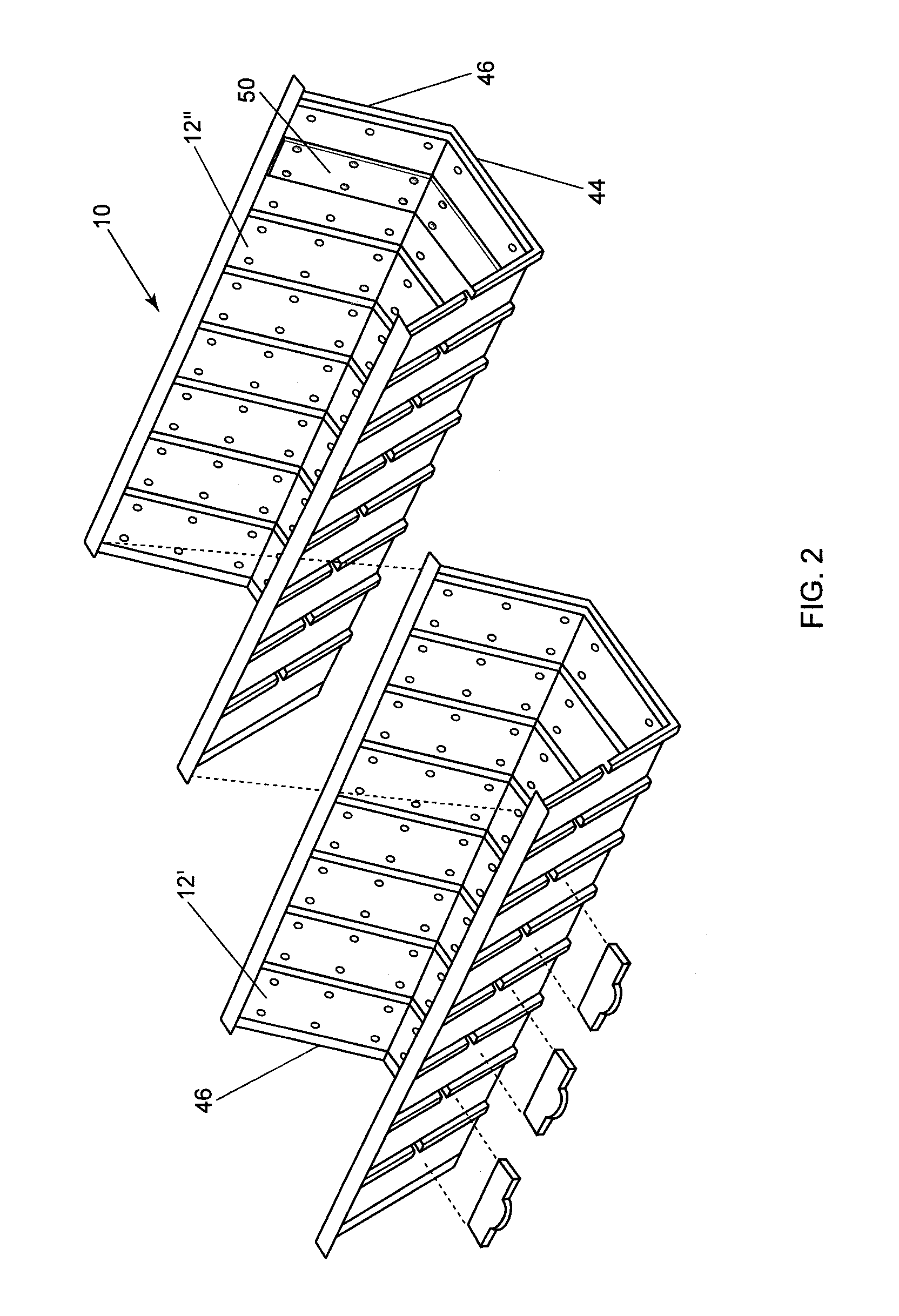
[0043]The structural lining system is comprised of a series of connected inverted channels with a trapezoidal cross section. The preferred structural liner system 10 is shown in FIGS. 1 and 2. FIG. 2 shows the liner system 10 of FIG. 1 comprised of a first liner channel 12′ affixed to a next liner channel 12″. Liner channels 12 are similarly affixed in series to a preferred length. Each liner channel 12 is constructed using an injection molding process which provides for tighter tolerances than a thermoformed process. By using the injection molding process, fewer components are required to be manufactured and used in construction of a lining system. Due to the tighter tolerances, the junction between a first liner channel 12′ and next liner channel 12″ can be abutted without a gasket or the like to form a water tight seal. The injection molded components, liner channels 12, and elbows 114, can be stacked or nested for minimizing transport spa...


PUM


Abstract

A lining system for a ditch or canal constructed with tight tolerances so a gasket is not required to connect liner channel sections. Each channel liner has a female slot on a first end and a male protrusion on a second end for adjoining channel liners. Flushing strips with male protrusions are installed in female slots in between channel beams. Flushing strips with variable Manning coefficients can be inserted based on a user's needs. Self-anchoring tabs can be inserted into anchoring slots on the outside of liner channels for anchoring the liner by soil compaction. Elbow sections can be used to change the direction of flow of the liquid. Elbow sections are adjoined to a liner channel similar to the adjoinment of in series channel liners to result in a desired angle for the change in direction.

Description

RELATED APPLICATIONS[0001]The present application claims priority to U.S. Provisional Application No. 61 / 990,815, filed May 9, 2014, assigned to Assignee hereof, and the specification of which is incorporated herein by reference.BACKGROUND OF THE INVENTION[0002]1. Field of the Invention (Technical Field)[0003]The present invention relates to a fluid transport lining system and more particularly to a variable Manning coefficient liner system, a gasket free liner adjoining system, system and a novel elbow system for changing the direction of the flow of liquids.[0004]2. Background Art[0005]Ditches formed in the earth for conveying water to a point or to an area of use have been common throughout the world for generations. Earthen ditches have been used to transport potable water, irrigation water, and other fluids and materials. Earthen irrigation ditches continue to be significant in the transportation of water because they are readily and inexpensively formed in almost any terrain.[...

Claims


Application Information

Patent Timeline
Patent Type & Authority Patents(United States)
IPC IPC(8): E02B5/02E02B13/00E02B5/00
CPCE02B5/02E02B5/00E02B13/00E02B3/12
Inventor SUAZO, KENNETH, L.
Owner AMERICAN LEAK DETECTION IRRIGATION INC
Learn More