
Medical emergency equipment

a technology for emergency equipment and medical devices, applied in medical science, surgery, diagnostics, etc., can solve the problems of unnecessary cleaning and sterilization, and achieve the effect of reducing patient manipulation and clear breathing passages

Inactive Publication Date: 2007-07-12
REYNOLDS CONNELL
View PDF64 Cites 2 Cited by
  • Summary
  • Abstract
  • Description
  • Claims
  • Application Information

AI Technical Summary

Benefits of technology

[0005] The present invention is a disposable head and neck immobilization assembly that is, in its function and reliability, substantially impervious to the effects of weather or other ambient effects, and requires a minimum of patient manipulation, as well as maintaining clear breathing passages while allowing the patient to see and hear what is happening.
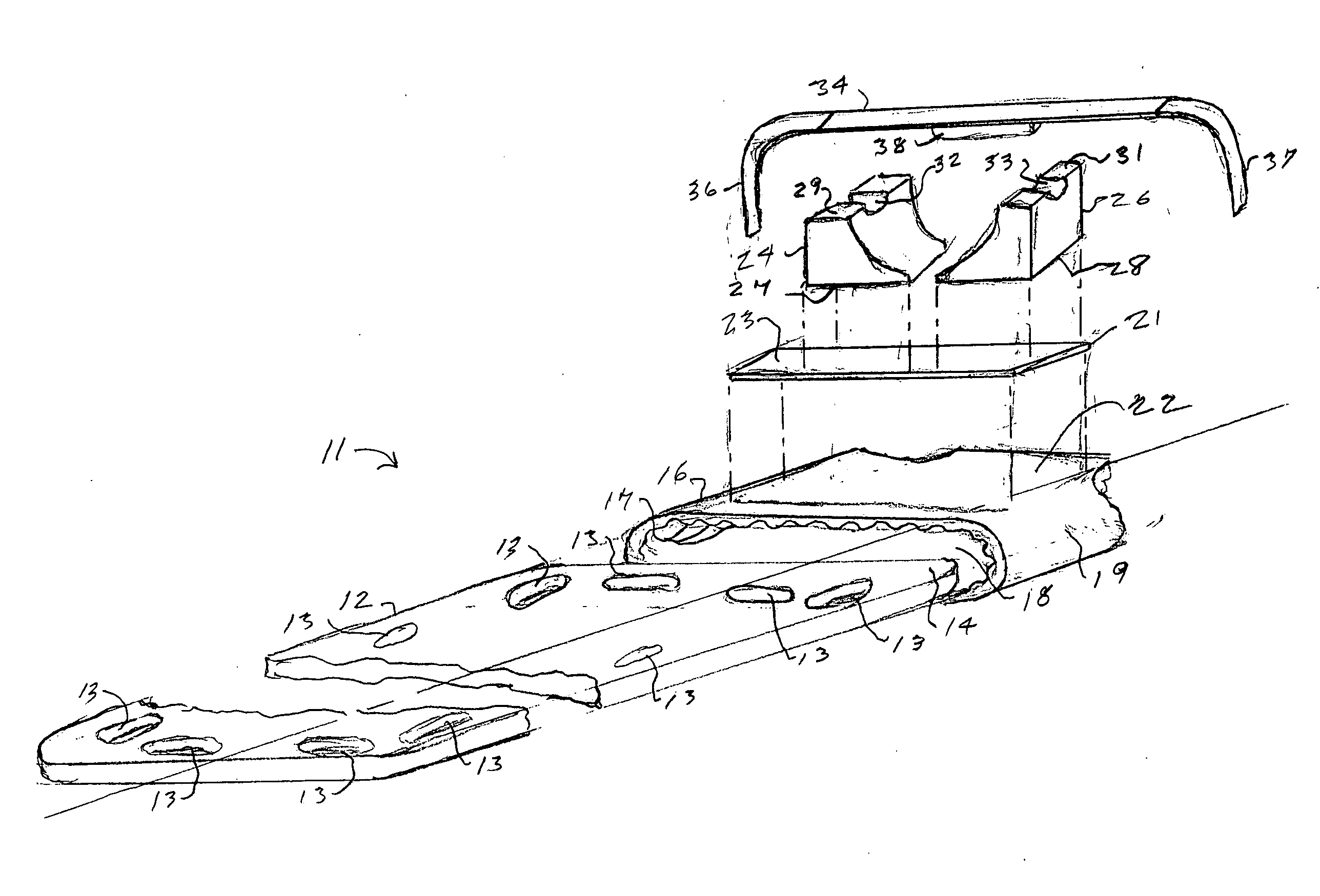
[0006] In a preferred embodiment of the invention, the assembly comprises a sleeve of cushioning material such as preferred plastic bubble wrap which is dimensioned to be slipped over the spine board at the head end thereof. The top surface of the sleeve is preferably smooth, and the interior surface of the sleeve contains the air bubbles. The top surface of the sleeve has one or two large areas of adhesion material, for example, patches of Velcro® loops which are located on either side of the top surface of the sleeve centerline or extend across the top surface of the sleeve and are cemented in place. First and second head restraining blocks of, for example, Styrofoam, have a bottom surface with Velcro® hooks for firmly attaching the blocks to the large area surfaces. The blocks are, in use, spaced to bear against the sides of the patient's head to immobilize it from side-to-side or lateral movement without the necessity of moving the patient's head. The movable blocks can easily be positioned to accommodate the lateral dimensions of the patient's head. When the patient is lying on the spine board, his head is cushioned by the bubble wrap material between the two head restraint blocks. The bubble wrap is preferable to a pillow or other cushioning device in that it does not raise the patient's head and therefore it affords cushioning without blocking the patient's airway, which, as pointed out, often results from a raised position of the head.
[0007] The patient's head is further immobilized by a single strap extending from and affixed to one side of the spine board bubble wrap sleeve, as by Velcro®, or other adhesion type material to the other side over the patient's forehead. The undersurface portion of the strap preferably has a light adhesive layer or pad thereon which lightly adheres to the patient's forehead to prevent slippages and to prevent vertical and rotational movement of the patient's head. In addition, it is desirable that the patient's body be strapped to the spine board to prevent bodily movement from possibly causing movement of the patient's head.
[0010] The invention has numerous advantages, principal among which are a quick immobilization of the patient, primarily his or her head with virtually no manipulation of the patient's head or neck, and while maintaining communication between the patient and emergency personnel. Additionally, the patient's sight, hearing and breathing are virtually unimpaired.
[0011] The apparatus of the invention is both simple in form and in use, and is made of materials that are readily available and not costly, which allows disposal of the apparatus after one use, a very important sanitary feature.
[0012] In addition to the foregoing advantages, in use, the application of the restraint assembly to the spine board and the patient is quickly accomplished, compared to prior art arrangements, which is an extremely desirable feature, inasmuch as speed is usually of the essence, and manipulation of the patient is minimized.

Problems solved by technology

As a consequence, cleaning and sterilization are unnecessary.

Method used


Image

  • Medical emergency equipment
  • Medical emergency equipment
  • Medical emergency equipment

Examples


first embodiment

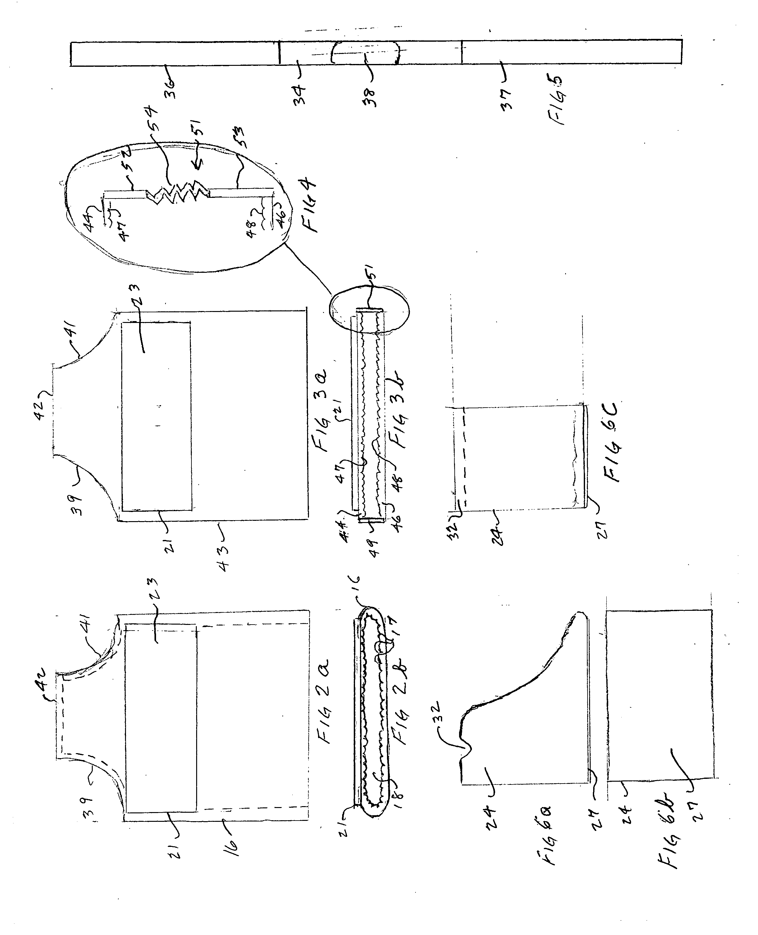
[0031]FIGS. 2a and 2b are, respectively, a plan view and a front elevation view of the sleeve 16 of the invention. In order that the hand holds 13 at the head end 14 of the spine board 12 be made accessible, sleeve 16 has large cut-out portions 39 and 41, extending as shown from the top or head or closed end 42 of sleeve 16 to the sides thereof. The cut-out portions 39 and 41 do not, in any way, impair the function of the assembly of the invention.

second embodiment

[0032]FIGS. 3a and 3b depict the invention in, respectively, a plan view and a front elevation view of a universal sleeve 43 which is readily usable with virtually any width spine board. In the figures the same reference numerals identify like parts with those of FIGS. 1, 2a, and 2b. Sleeve 43 comprises an upper member 44 of bubble wrap material and a lower member 46, with the top surface of member 44 being smooth and the bubble surface 47 thereof facing the bubble surface 48 of member 46, as shown in FIG. 3b. Members 44 and 46 are joined at their substantially parallel side ends by an elastic material 49 and 51 as shown in FIG. 3b, the details of which are shown in FIG. 4.

[0033] As can be seen in FIG. 4, strip 51 (and strip 49) comprises a first strip 52 of Velcro®, for example, which is cemented to the side edge of bubble wrap member 44, as shown, and a second strip 53 of Velcro® material is cemented to the side edge of member 46. The material of the strip 52 and 53 are preferably...


PUM


Abstract

A medical emergency head and neck stabilization system for use on a patient carrying device such as a spine board includes a sleeve of cushioning material which fits over the end of the spine board. First and second side head restraints are affixable to the cushioning material and a head retaining strap is designed to pass over the patient's head, such as the forehead, and to be fixed in position on or around the sleeve.

Description

FIELD OF THE INVENTION [0001] The present invention relates generally to medical emergency equipment and, more particularly, to a disposable patient head and neck immobilization assembly usable in extremes of weather as well as normally. BACKGROUND OF THE INVENTION [0002] In medical emergencies and accidents, it is often necessary to immobilize a victim or patient prior to transporting the patient to a medical facility. Typically, a patient is placed on an immobilization board, known as a spine board, which maintains the patient in a flat, straight position. Additionally, in order to prevent further injury, the patient's head and neck must be further immobilized, typically by securing the patient's head to the spine board. Prior art devices for accomplishing such immobilizations are complex in design, difficult to apply and remove, and costly to manufacture. In most injury cases, one of the most important steps to be taken is the quick and safe immobilization of the patient. If immo...

Claims


Application Information

Patent Timeline
IPC IPC(8): A61B19/00
CPCA61G1/01A61G1/044A61G1/04
Inventor REYNOLDS, CONNELL
Owner REYNOLDS CONNELL
Learn More