
Plunger rod and syringe

a syringe and syringe technology, applied in the field of syringes, can solve the problems of not being able to fill a desired drug solution in a syringe, not being able to achieve the effect of enhancing visible identifiability, improving visual identifiability, and improving visual identifiability

Inactive Publication Date: 2016-04-12
DAIKYO SEIKO LTD
View PDF14 Cites 2 Cited by
  • Summary
  • Abstract
  • Description
  • Claims
  • Application Information

AI Technical Summary

Benefits of technology

The present invention provides a plunger rod for a syringe that can easily be identified visually, even without the need for additional indication members. The plunger rod is colored in part or in whole, making it easy to identify the syringe by simply taking a glance at it. This feature helps to avoid the accident of administering a wrong drug solution to a patient, as the coloring of the plunger rod is effective even in the case of pre-filled syringes with drug solutions. The plunger rod is easy to manufacture and does not significantly affect the functionality, safety, and sanitariness of the syringe. The invention provides a useful syringe that is visually identifiable and has enhanced practical utility and convenience.

Problems solved by technology

However, none of the conventional measures are such that would enhance the visual identifiability of a syringe itself, and permit identifying a drug solution filled in a syringe barrel and obtaining information or the like on a patient, to which the filled drug solution is to be administered, by simply taking a glance.
Moreover, the size of an area in an indication member such as a label, where information can be written, is limited, and even with such an indication member being arranged, the visual identifiability of a syringe can by no means be considered to be high.
It is, therefore, not easy to fill a desired drug solution in a syringe while completely avoiding misidentification or confusion.
Accordingly, it is essential to absolutely avoid such a situation that the high-level quality, function, sanitariness and safety required for the syringe would be impaired even if an improvement can be made in the visual identifiability of the syringe itself.

Method used


Image

  • Plunger rod and syringe
  • Plunger rod and syringe
  • Plunger rod and syringe

Examples


Embodiment Construction

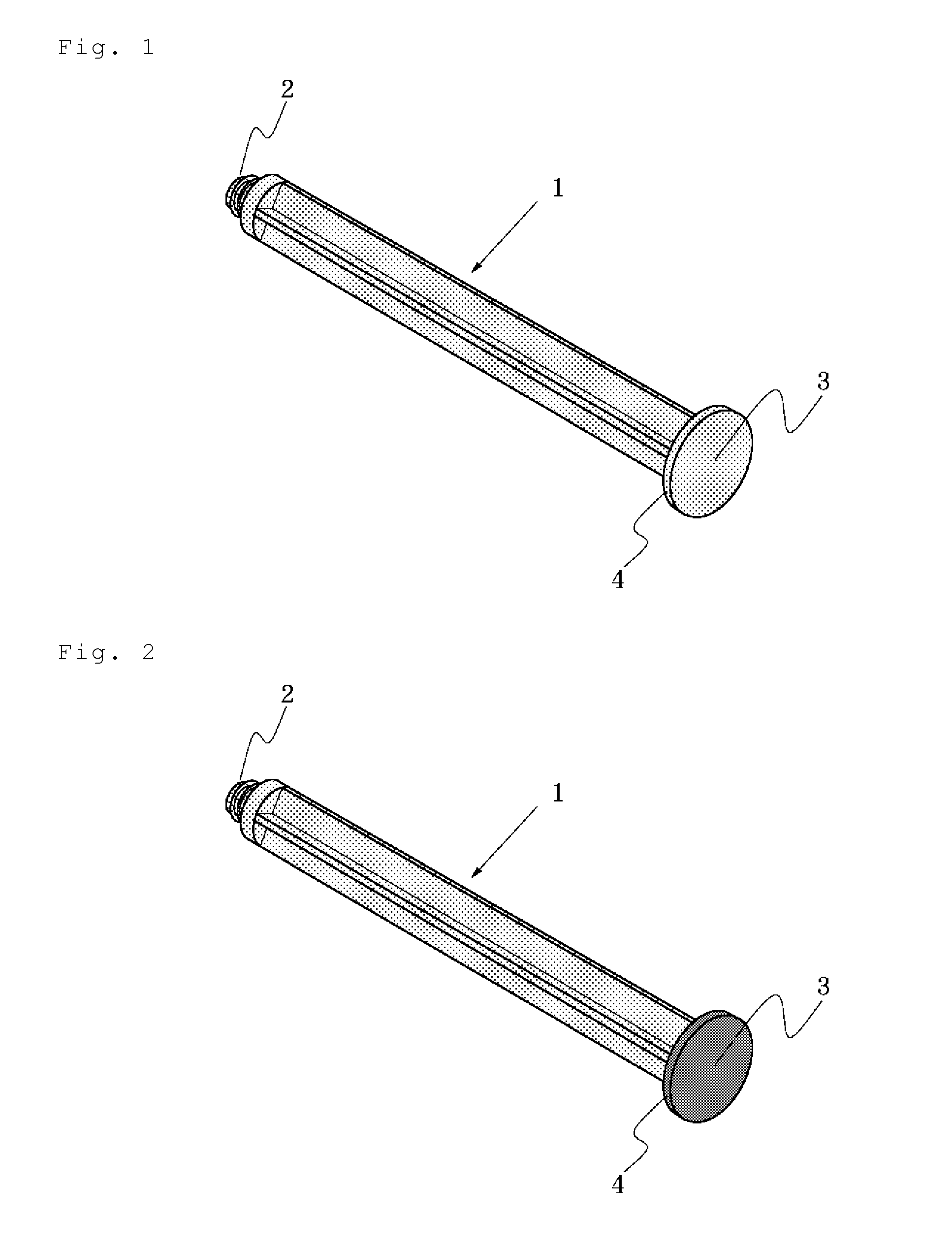
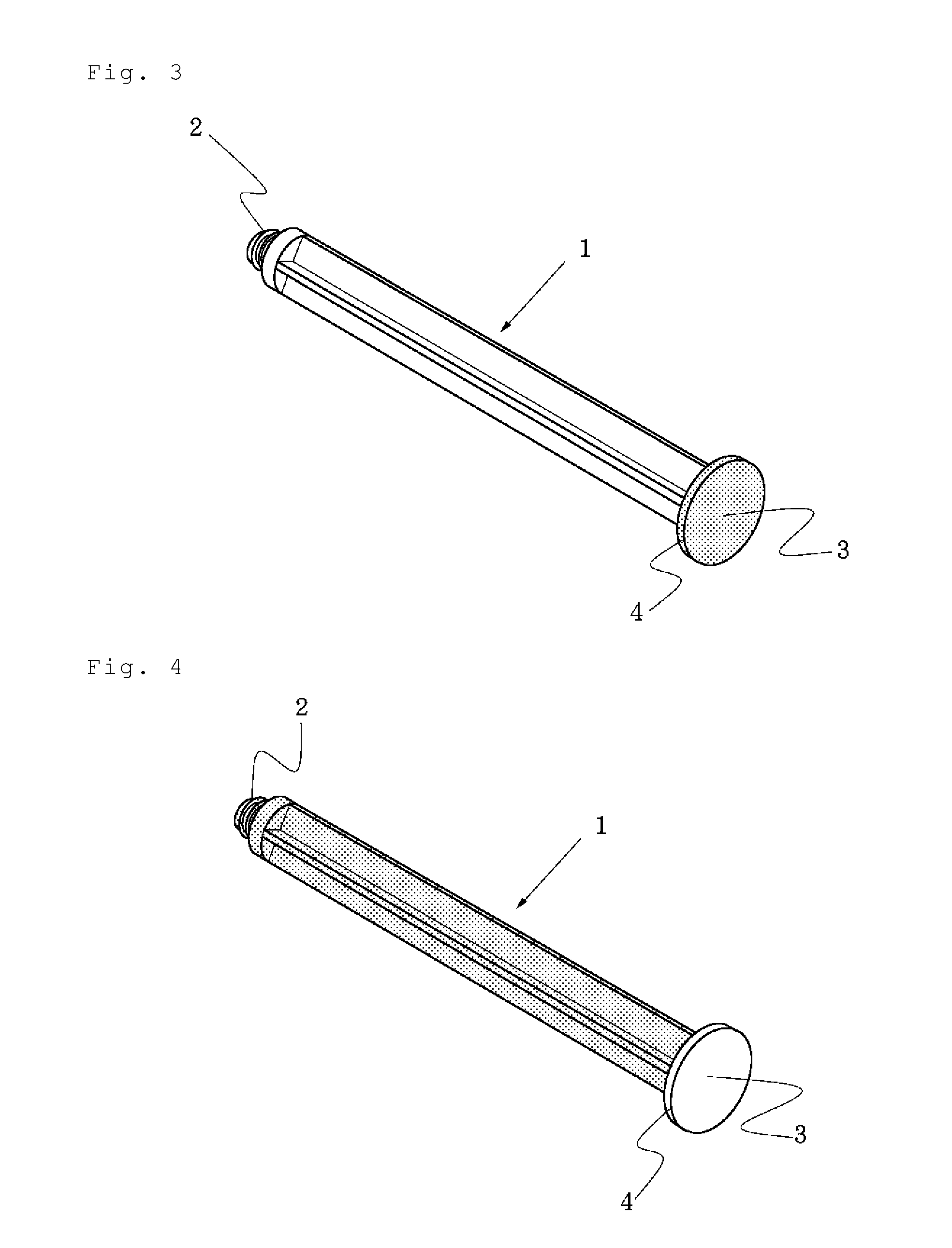
[0014]The present invention will hereinafter be described in detail based on preferred embodiments. Descriptions will be made with reference to drawings that illustrate examples of certain preferred embodiments of the plunger rod according to the present invention. The plunger rod according to the present invention is characterized in that it is colored in part or in whole. FIG. 1 and FIG. 2 are perspective views showing examples of the plunger rod according to the present invention, both of which are colored in whole. FIG. 3, FIG. 4 and FIG. 6 are perspective views showing other examples of the plunger rod according to the present invention, all of which are colored only in part. A description will first be made about advantageous effects available from the use of the invention plunger rod constructed as described above.

[0015]Considering that, if a syringe can be provided with enhanced visible identifiability by a simple measure without impairment to the function and safety require...


PUM


Abstract

Disclosed is a plunger rod for a syringe. The plunger rod is useful for sliding a piston within a syringe barrel. The plunger rod is characterized in that it is colored in part or in whole. The syringe is also disclosed. According to such plunger rods, even plural syringes of exactly the same external appearance and configuration can be applied with features that make it possible to readily and visually identify them by simply taking a glance at their appearances without needing a measure such as applying indication members such as labels on them. Further, the use of such plunger rods makes it possible to provide syringes of significantly enhanced visual identifiability without impairing high-level quality, functions, sanitariness and safety required for the syringes.

Description

[0001]This application is a U.S. national phase filing under 35 U.S.C. §371 of PCT Application No. PCT / JP2008 / 053603, filed Feb. 29, 2008, which is hereby incorporated in its entirety by reference.TECHNICAL FIELD[0002]This invention relates to a plunger rod and a syringe, and more specifically, is concerned with a plunger rod for a syringe, said plunger rod being colored in part or in whole, and also with a high-identifiability syringe making use of the plunger rod.BACKGROUND ART[0003]An administration of a drug solution to a patient by a syringe is carried out by a procedure such as that to be described hereinafter. After the drug solution is first drawn from an ampoule or vial and filled in a syringe barrel by using a plunger rod, the plunger rod is slowly pushed into the syringe barrel so that the drug solution is injected directly or via an infusion tube into a blood vessel or the like of the patient. Syringes, which are used as described above, are substantially the same in con...

Claims


Application Information

Patent Timeline
Patent Type & Authority Patents(United States)
IPC IPC(8): A61M5/315A61M5/31
CPCA61M5/31511A61M2005/3121A61M2205/583A61M2205/6081
Inventor KAWAMURA, HIDEAKITOGASHI, HIROSHI
Owner DAIKYO SEIKO LTD
Learn More