
Method for monitoring the integrity of an eddy current inspection channel

a technology of eddy current and inspection channel, which is applied in the direction of instruments, measurement devices, scientific instruments, etc., can solve the problems of restricting the application of this method, patented methods may become difficult to apply to a complex probe design, and non-destructive examination of components, etc., to achieve accurate assessment of the condition of the whole system

Active Publication Date: 2016-04-19
OLYMPUS NDT
View PDF3 Cites 0 Cited by
  • Summary
  • Abstract
  • Description
  • Claims
  • Application Information

AI Technical Summary

Problems solved by technology

Eddy current field conditions associated with problematic component conditions (including flaws, conductivity variation, thickness, etc) can then lead to non-destructive examination of the component.
Although the known method allows determining the correct functioning of the eddy current system, there are some limitations, which restrict the application of this method.
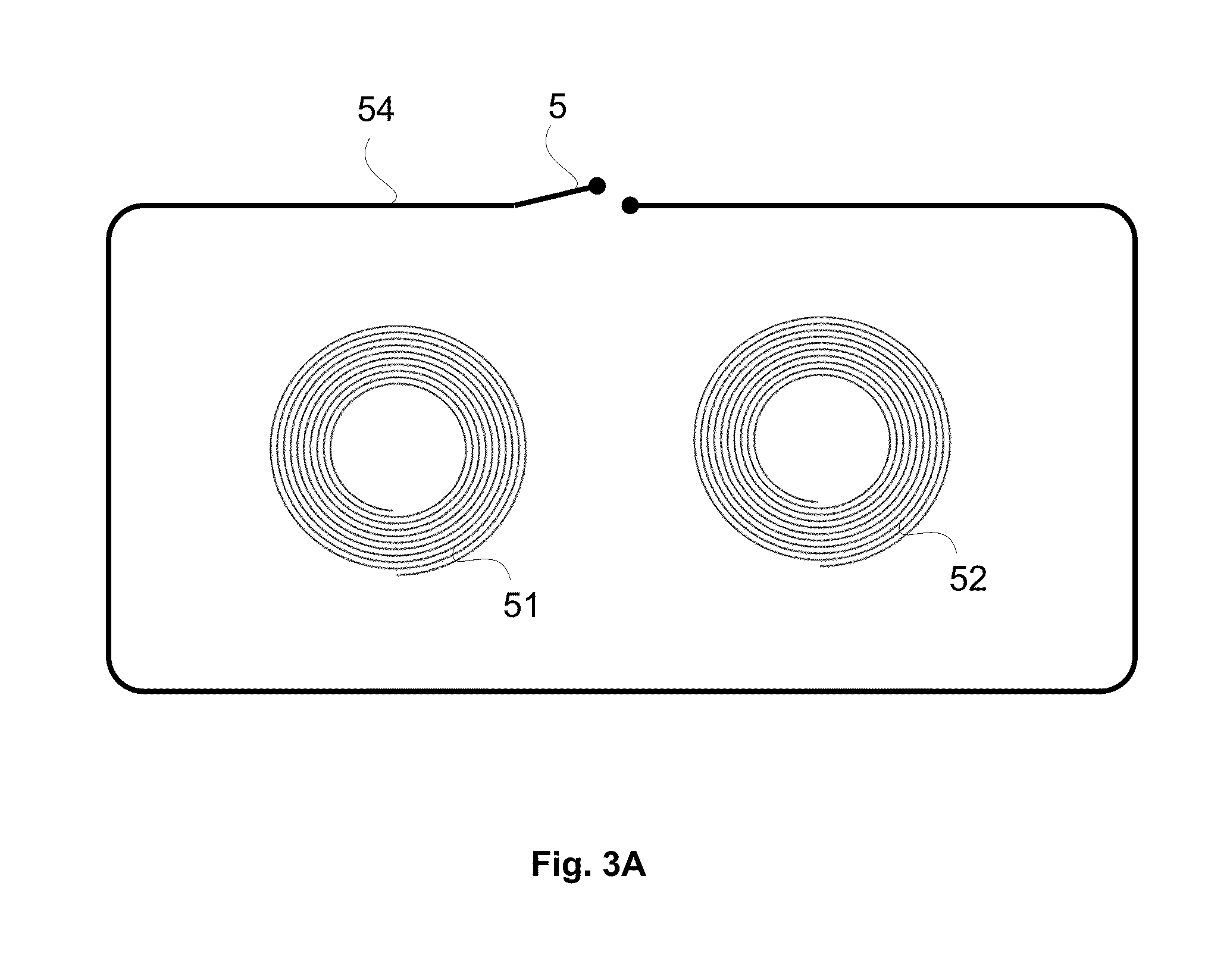
In addition, the patented method may become difficult to apply to a complex probe design, which includes a multiple coil array.
Nonetheless, the complexity of the U.S. Pat. No. 8,421,471 invention limits its applications.

Method used


Image

  • Method for monitoring the integrity of an eddy current inspection channel
  • Method for monitoring the integrity of an eddy current inspection channel
  • Method for monitoring the integrity of an eddy current inspection channel

Examples


Embodiment Construction

[0032]The test loop of the present invention is based on eddy current basics. Thus, when a shielding loop is positioned around an eddy current test coil, a signal will be induced in the loop and this signal will change the magnitude and phase of current flowing in the coil. The detection of these changes enables checking the ECA inspection system functionality.

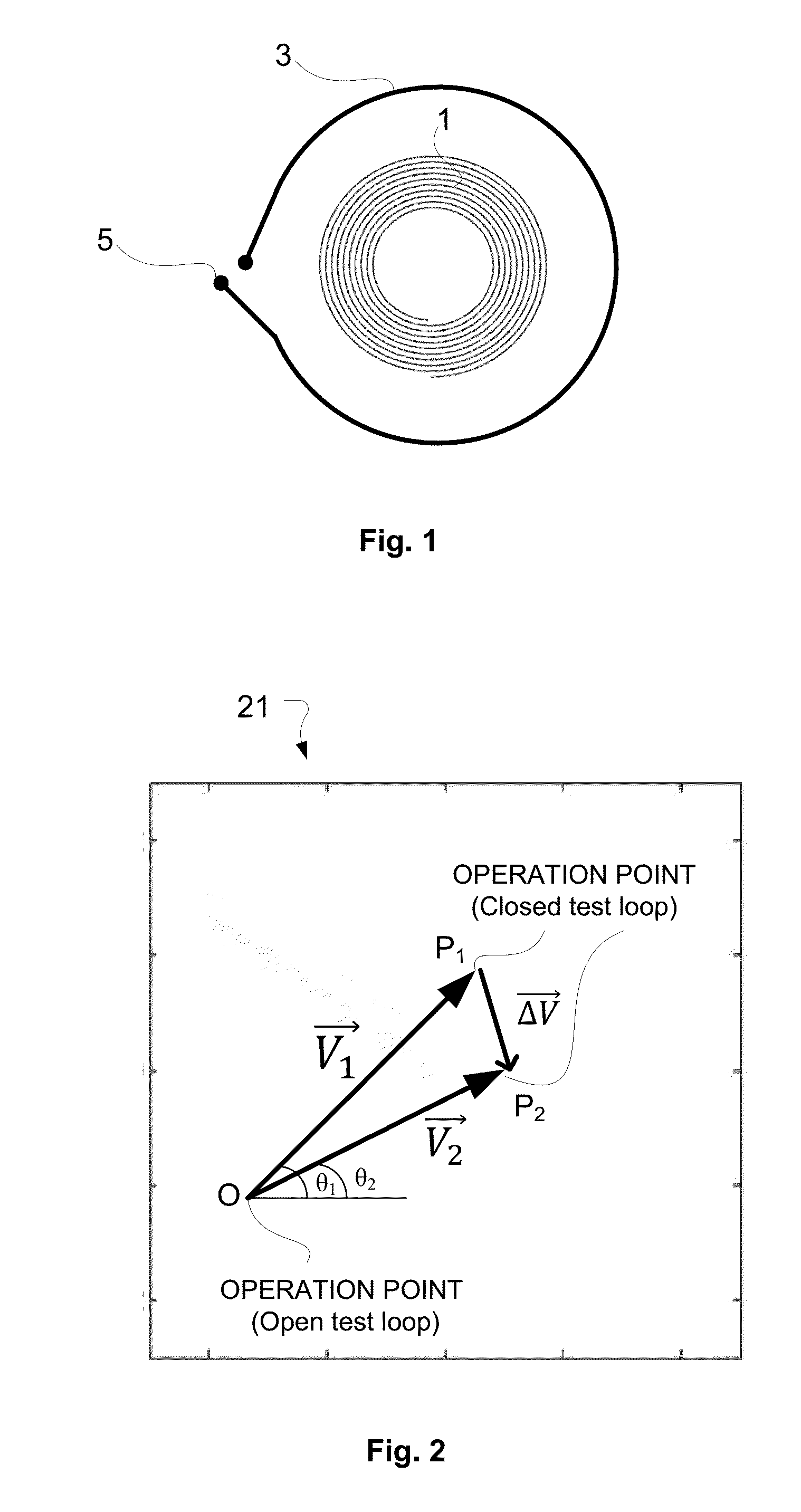
[0033]FIG. 1 is a simple configuration of the test loop in one channel, which is composed of a single coil 1, which is being used for both the generation and reception of the eddy current signals. The test loop 3 in this case consists of a conductive circuit, which turns around the inspection coil 1. The switch 5 is utilized to activate test loop 3. Once the switch 5 is closed, an eddy current is induced in the test loop 3. Consequently, the coil 1 impedance is changed. However, when the coil 1 is broken, it does not induce current in test loop 3 and consequently, shows no changes in coil's 1 impedance associated with the swit...


PUM

PropertyMeasurementUnit
timeaaaaaaaaaa
eddy current object testingaaaaaaaaaa
eddy current probeaaaaaaaaaa

Abstract

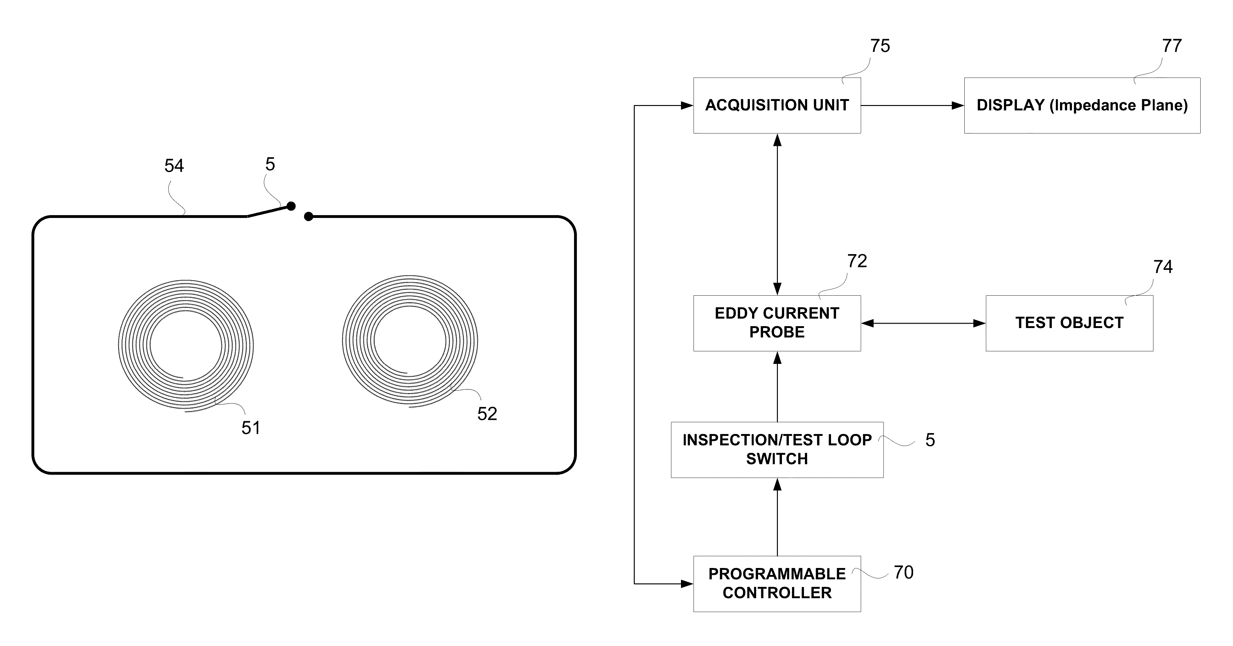
An eddy current object testing system includes an EC probe and an acquisition channel which is configured to receive an EC signal from the EC probe and to generate a visual output, namely an impedance plane representation, of the output. A display is coupled to the acquisition channel to display the visual output. The at least one probe is provided with a test loop substantially surrounding it and has a series switch which can be selectively closed or opened to thereby cause the image plane to assume a state that is indicative of a fault, if any, in the EC probe.

Description

FIELD OF THE INVENTION[0001]The present invention relates to non-destructive testing and inspection systems (NDT / NDI) and, more particularly, to Eddy Current (EC) or Eddy Current Array technology (ECA), employing eddy current probes with a test loop linked to it, which allows checking the integrity of the testing system.BACKGROUND OF THE INVENTION[0002]Eddy current inspection is commonly used as a non-destructive method to detect flaws in surfaces of manufactured components fabricated from a conductive material, such as bars, tubes, and special parts for automotive, aeronautic or energy industries.[0003]Typical eddy current sensor configurations are impedance bridge, pitch-catch (alternatively called reflection or transmit-receive) and differential, but can also include more complex combinations such as pitch-catch with differential receivers, multi-differential, etc.[0004]Each eddy current system regardless of its configuration is composed of coils in different shapes. In a standar...

Claims


Application Information

Patent Timeline
Patent Type & Authority Patents(United States)
IPC IPC(8): G01R33/12G01N27/90
CPCG01N27/90G01N27/9033G01N27/9006
Inventor LEPAGE, BENOIT
Owner OLYMPUS NDT
Learn More