Eureka AIR delivers breakthrough ideas for toughest innovation challenges, trusted by R&D personnel around the world.

Tracking objects on a touch surface

a technology of touch surface and object, applied in the field of tracking objects on the touch surface, can solve the problems of difficulty in properly detecting the touch surface at all, the degree of interaction between the touching object and the touch surface may vary both, and the task is demanding, so as to improve the accuracy of potentially false peaks

Active Publication Date: 2016-04-19
FLATFROG LAB
View PDF21 Cites 33 Cited by
  • Summary
  • Abstract
  • Description
  • Claims
  • Application Information

AI Technical Summary

Benefits of technology

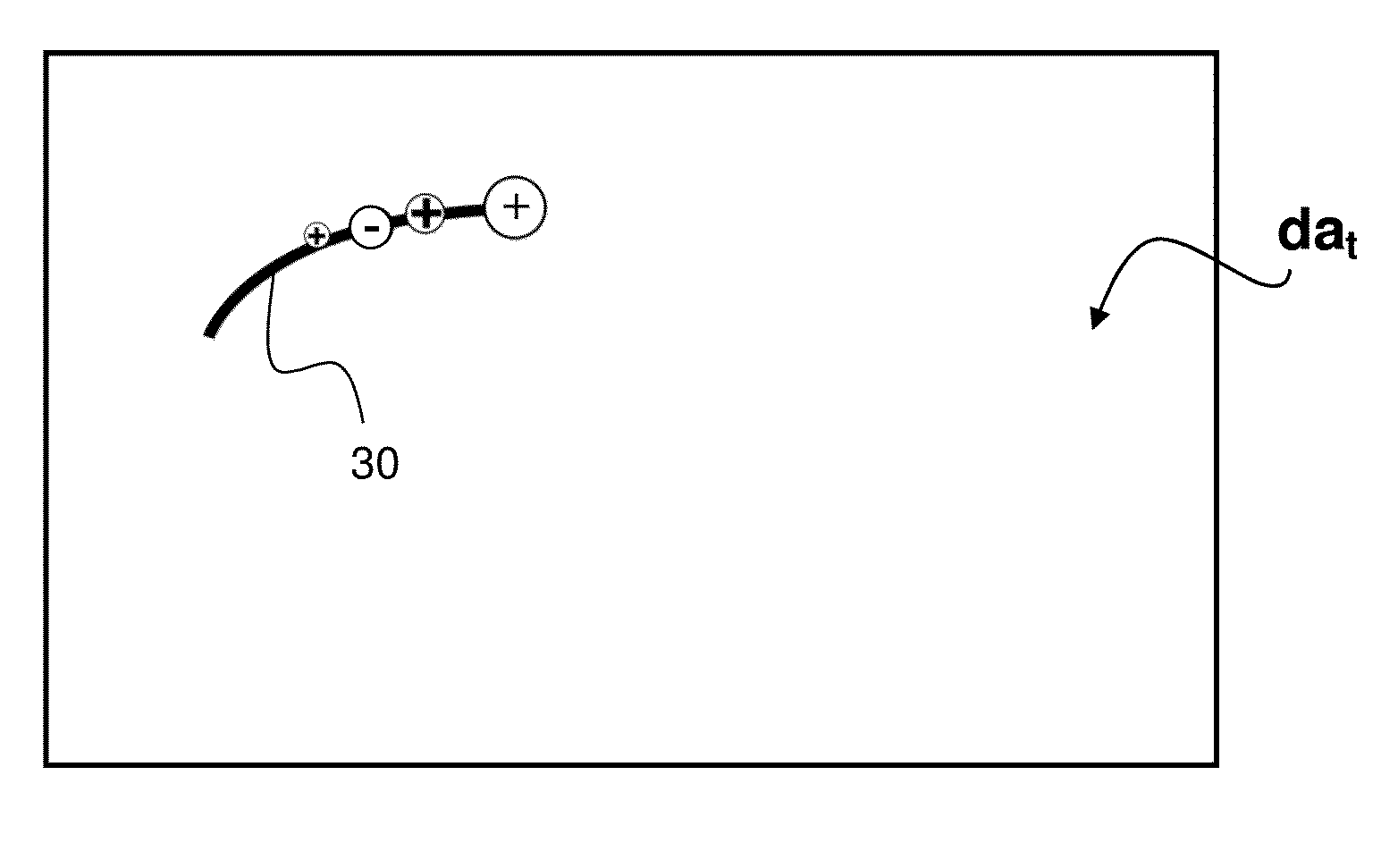
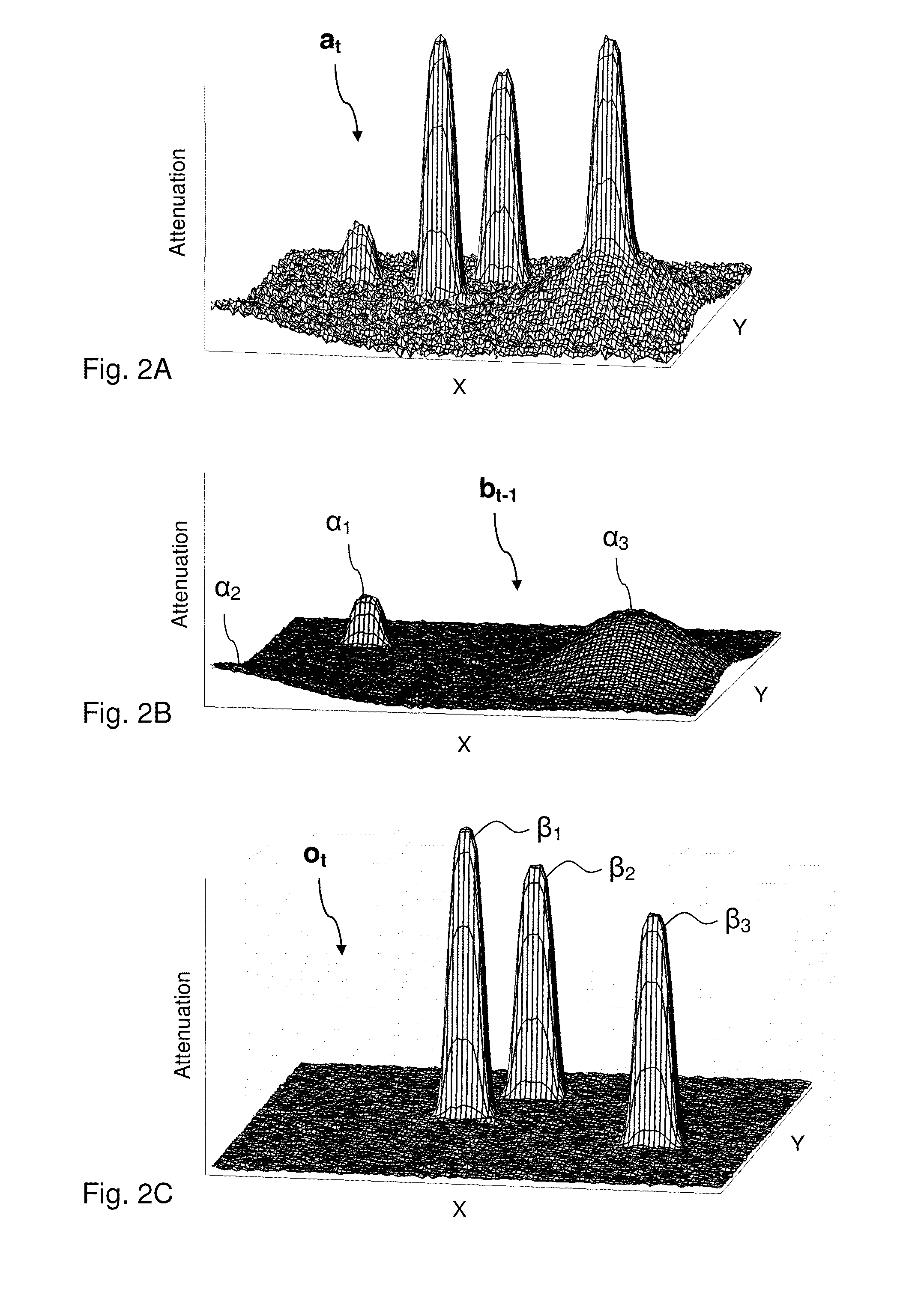
[0018]The method of the first aspect validates the positive and negative apparent peaks, to identify potentially false peaks in the interaction map, and updates the movement trajectories based on the outcome of the validation. In contrast to true peaks, false peaks are peaks that do not correspond to an object that is controlled by the user. One challenge when identifying the potentially false peaks is to reduce the number of apparent peaks that are erroneously identified as new touches, while ensuring that those apparent peaks that indeed represent new touches are not mistaken for false peaks. Errors introduced into the movement trajectories may propagate, and even be enhanced, as the movement trajectories are updated over time. To contain this risk, the method of the first aspect applies the first and / or second heuristic which makes use of inherent characteristics of the touch-sensitive apparatus when validating the apparent peaks. These inherent characteristics relate to how true peaks are known to show up in the interaction map. For example, an existing object, moving or not, will show up as an apparent peak in the interaction map at a location relatively close to its previous location, i.e. its location at the preceding time point. Furthermore, new objects that are brought into proximity with the touch surface will appear as positive peaks, i.e. peaks of locally increased interaction in the interaction map.
[0022]In one embodiment, the first heuristic is designed to further require said one or more of the negative apparent peaks to be located outside the movement trajectories. Such an embodiment may e.g. be applicable when the interaction map is known to represent objects by negative apparent peaks, and it is thus conceivable that negative apparent peaks occur along the movement trajectories. To improve the accuracy of the potentially false peaks that are identified, the first heuristic may be designed to exclude such negative apparent peaks.
[0025]In one embodiment, the second heuristic further requires, to designate the positive apparent peak as a potentially false peak, that the positive apparent peak is included in said set of non-matched apparent peaks. This may prevent a true peak representing an object that crosses an existing movement trajectory from being identified as a potentially false touch.
[0027]In one embodiment, the step of updating comprises: evaluating, based on the potentially false peaks, the positive and negative apparent peaks for determination of a current location for at least part of the movement trajectories; evaluating, based on the potentially false peaks, the positive and negative apparent peaks for identification of new touches; and adding the location of each of said new touches as a starting point of a new movement trajectory. In one embodiment, the step of updating comprises: preventing the identification of new touches based on the potentially false peaks. In one embodiment, the method operates in successive repetitions of the steps of processing and updating, and the identification of new touches based on the potentially false peaks is prevented during a number of successive repetitions for at least part of the potentially false peaks, thereby postponing the identification of new touches.

Problems solved by technology

These interferences may vary not only over time but also across the touch surface, making it difficult to properly detect the touches on the touch surface at all times. Furthermore, the degree of interaction between a touching object and the touch surface may vary both over time and between different objects.
The combination of several touches, complex gestures as well as temporal and spatial variations of interaction and interferences will make the identification of touches a demanding task.
The user experience may be hampered if, e.g., an ongoing gesture on a touch screen is interrupted by the system failing to detect certain touches during the gesture.
To the extent that such a suppression is incomplete, or other types of interferences are present, the 2D representation may still contain false peaks that are mistaken for touching objects.
One challenge when identifying the potentially false peaks is to reduce the number of apparent peaks that are erroneously identified as new touches, while ensuring that those apparent peaks that indeed represent new touches are not mistaken for false peaks.

Method used


Image

  • Tracking objects on a touch surface
  • Tracking objects on a touch surface
  • Tracking objects on a touch surface

Examples


Embodiment Construction

[0054]Before describing embodiments of the invention, a few definitions will be given.

[0055]A “touch object” or “touching object” is a physical object that actively or intentionally touches, or is brought in sufficient proximity to, a touch surface so as to be detected by one or more sensors in the touch system. The physical object may be animate, e.g. a finger, or inanimate.

[0056]An “interaction” occurs when the touch object affects a parameter measured by the sensor.

[0057]An “interaction strength” is a relative or absolute measure of the degree of interaction.

[0058]An “interaction map” or “interaction pattern” is a two-dimensional (2D) distribution of interaction across the touch surface, or a portion thereof. If the “interaction map” contains attenuation values, it is also denoted an “attenuation map” or “attenuation pattern”.

[0059]A “touch” denotes a point of interaction as seen in the interaction pattern. A touch may be associated with different touch parameters, such as a loca...


PUM


Abstract

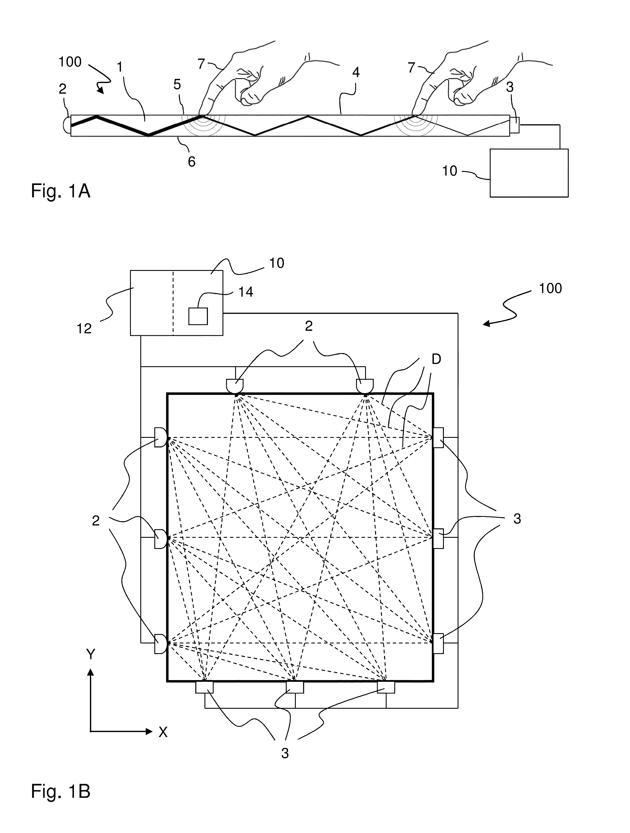
A device implements a method of tracking objects on a touch surface of an FTIR based touch-sensitive apparatus.

Description

CROSS-REFERENCE TO RELATED APPLICATIONS[0001]The present application claims the benefit of Swedish patent application No. 1151208-4, filed 16 Dec. 2011, and U.S. provisional application No. 61 / 576,550, filed 16 Dec. 2011, both of which are incorporated herein by reference.TECHNICAL FIELD[0002]The present invention relates to techniques for tracking objects on a touch surface, in particular a touch surface of a touch-sensitive apparatus that operates by propagating light inside a light transmissive panel from a plurality of incoupling points to a plurality of outcoupling points so as to illuminate the touch surface from within the panel.BACKGROUND ART[0003]Touch sensing systems (“touch systems”) are in widespread use in a variety of applications. Typically, the touch systems are actuated by a touch object such as a finger or stylus, either in direct contact, or through proximity (i.e. without contact), with a touch surface. Touch systems are for example used as touch pads of laptop c...

Claims


Application Information

Patent Timeline
Patent Type & Authority Patents(United States)
IPC IPC(8): G06F3/041G06F3/044G06F3/042G06F3/0488
CPCG06F3/044G06F3/0418G06F3/0421G06F3/04883G06F2203/04109G06F2203/04111G06F3/04186
Inventor CHRISTIANSSON, TOMASOHLSSON, NICKLASBJORKLUND, ANDREAS
Owner FLATFROG LAB
Why Eureka
Eureka Blog
Learn More