Tracking objects on a touch surface

Inactive Publication Date: 2016-07-14
FLATFROG LAB
View PDF0 Cites 32 Cited by
  • Summary
  • Abstract
  • Description
  • Claims
  • Application Information

AI Technical Summary

Benefits of technology

[0021]It should also be noted that the first and/or second heuristic may be able to identify false peaks originating from other types of interferences, including but not limited to incomplete contamination compensation, ambient light and measurement noise.
[0022]In one embodiment, the first heuristic is designed to further require said one or more of the negative apparent peaks to be located outsid

Problems solved by technology

These interferences may vary not only over time but also across the touch surface, making it difficult to properly detect the touches on the touch surface at all times. Furthermore, the degree of interaction between a touching object and the touch surface may vary both over time and between different objects.
The combination of several touches, complex gestures as well as temporal and spatial variations of interaction and interferences will make the identification of touches a demanding task.
The user experience may be hampered if, e.g., an ongoing

Method used


Image

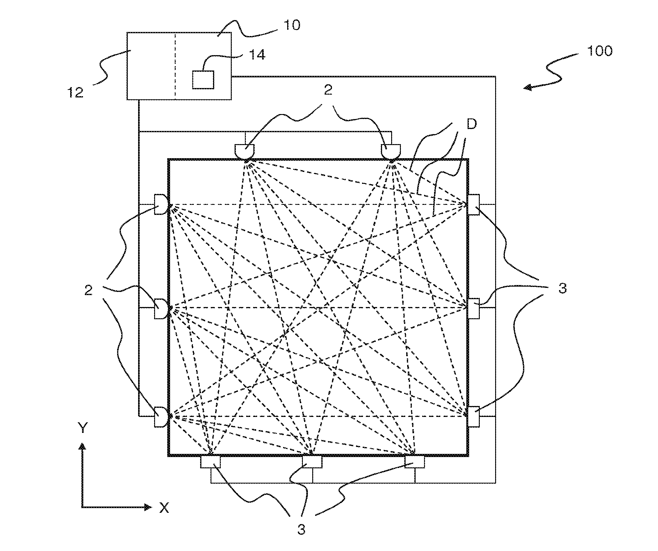
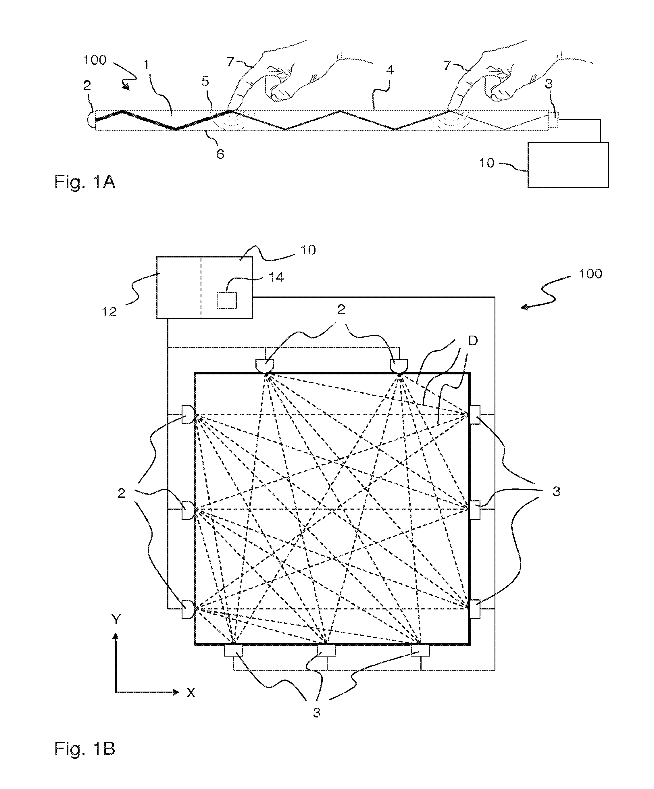
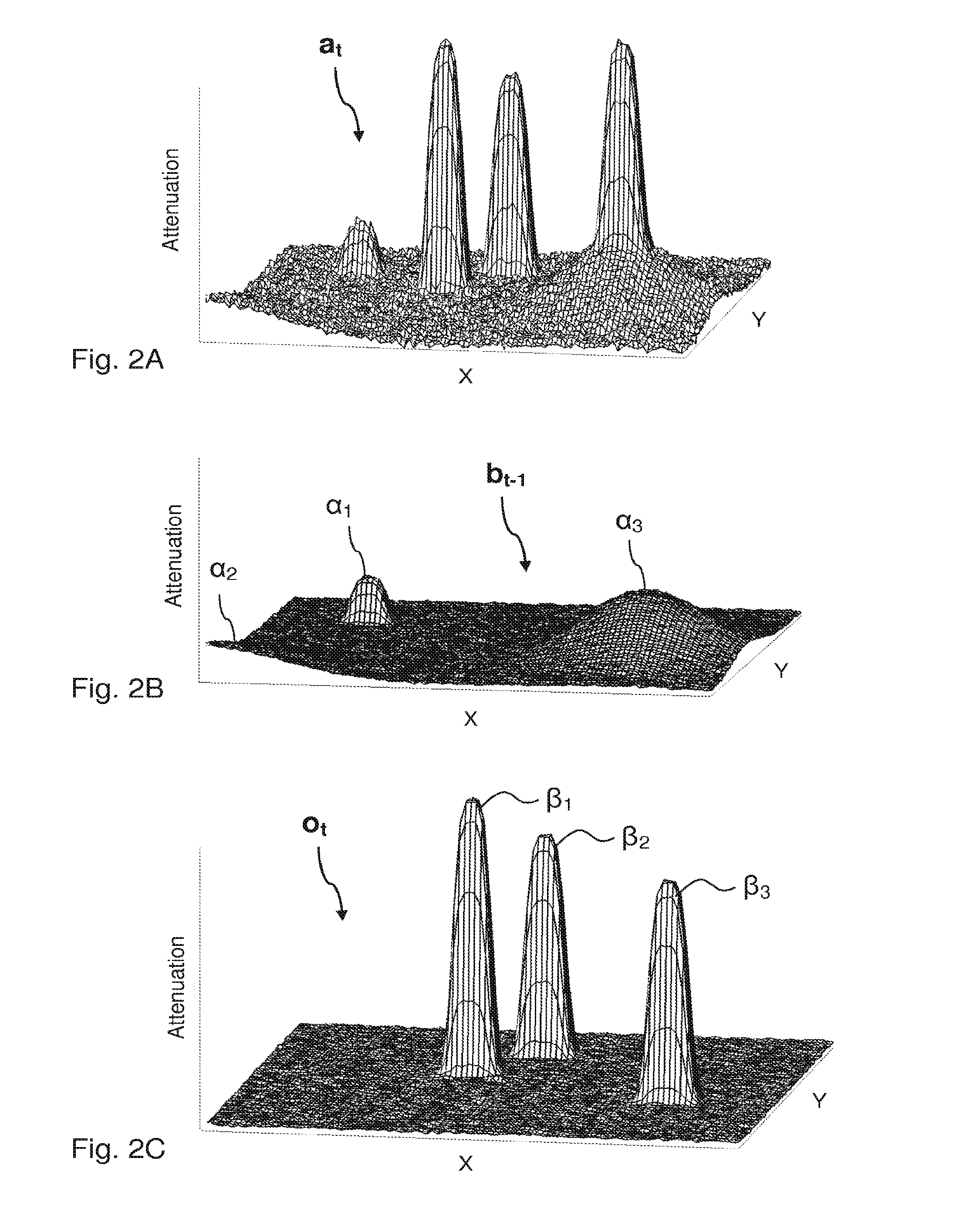
  • Tracking objects on a touch surface
  • Tracking objects on a touch surface
  • Tracking objects on a touch surface

Examples


Embodiment Construction

[0054]Before describing embodiments of the invention, a few definitions will be given.

[0055]A “touch object” or “touching object” is a physical object that actively or intentionally touches, or is brought in sufficient proximity to, a touch surface so as to be detected by one or more sensors in the touch system. The physical object may be animate, e.g. a finger, or inanimate.

[0056]An “interaction” occurs when the touch object affects a parameter measured by the sensor.

[0057]An “interaction strength” is a relative or absolute measure of the degree of interaction.

[0058]An “interaction map” or “interaction pattern” is a two-dimensional (2D) distribution of interaction across the touch surface, or a portion thereof. If the “interaction map” contains attenuation values, it is also denoted an “attenuation map” or “attenuation pattern”.

[0059]A “touch” denotes a point of interaction as seen in the interaction pattern. A touch may be associated with different touch parameters, such as a loca...


PUM


Abstract

A device implements a method of tracking objects on a touch surface of an FTIR based touch-sensitive apparatus. An interaction map is generated that indicates local changes in interaction on the touch surface. The interaction map is processed for identification of positive and negative peaks that represent a locally increased and decreased interaction in the interaction map, respectively. To suppress the impact of interferences, a dedicated first heuristic and/or second heuristic is applied to identify potentially false peaks among the positive peaks. The first heuristic designates a positive peak as a potentially false peak when the positive peak is deemed to be associated with one or more of the negative peaks. The second heuristic designates a positive peak as a potentially false peak when the positive peak is deemed to be located along one of the movement trajectories. Movement trajectories of all objects deemed to exist on the touch surface at a preceding time point are then updated while taking the potentially false peaks into account.

Description

CROSS-REFERENCE TO RELATED APPLICATIONS[0001]This application is a continuation-in-part of, and claims priority under 35 U.S.C. §120 to, U.S. patent application Ser. No. 14 / 365,468, filed on 13 Jun. 2014, which is the National Stage under 35 U.S.C. §371 of PCT International Application No. PCT / SE2012 / 051368, filed 10 Dec. 2012, which claims priority to Swedish patent application No. 1151208-4, filed 16 Dec. 2011, and to provisional U.S. patent application No. 61 / 576,550, filed 16 Dec. 2011, the entire contents of all of which are incorporated herein by reference.TECHNICAL FIELD[0002]The present invention relates to techniques for tracking objects on a touch surface, in particular a touch surface of a touch-sensitive apparatus that operates by propagating light inside a light transmissive panel from a plurality of incoupling points to a plurality of outcoupling points so as to illuminate the touch surface from within the panel.BACKGROUND ART[0003]Touch sensing systems (“touch systems...

Claims


Application Information

Patent Timeline
IPC IPC(8): G06F3/041G06T7/00G06F3/042
CPCG06F3/0418G06F3/0421G06F2203/04109G06T2207/30241G06F2203/04104G06T7/004
Inventor CHRISTIANSSON, TOMASOHLSSON, NICKLASBJORKLUND, ANDREAS
Owner FLATFROG LAB
Why Eureka
Try Eureka