
Gear transmission and derailleur system

a technology of gear transmission and derailleur, which is applied in the direction of gear, cycle equipment, transportation and packaging, etc., can solve the problems of cable ability and tendency to stretch, heavy and expensive shifter, and bulky cables, so as to improve the accuracy, reduce or eliminate the effect of complications

Inactive Publication Date: 2016-05-03
PAHA DESIGNS
View PDF670 Cites 19 Cited by
  • Summary
  • Abstract
  • Description
  • Claims
  • Application Information

AI Technical Summary

Benefits of technology

[0006]Accordingly, there has been a long-felt and unmet need to provide a gear transmission and derailleur system that improves shifting accuracy and reduces or eliminates complications associated with chain slack. There has further been a long-felt and unmet need to provide a derailleur system with linear translation features that improves accuracy and is easy to use.
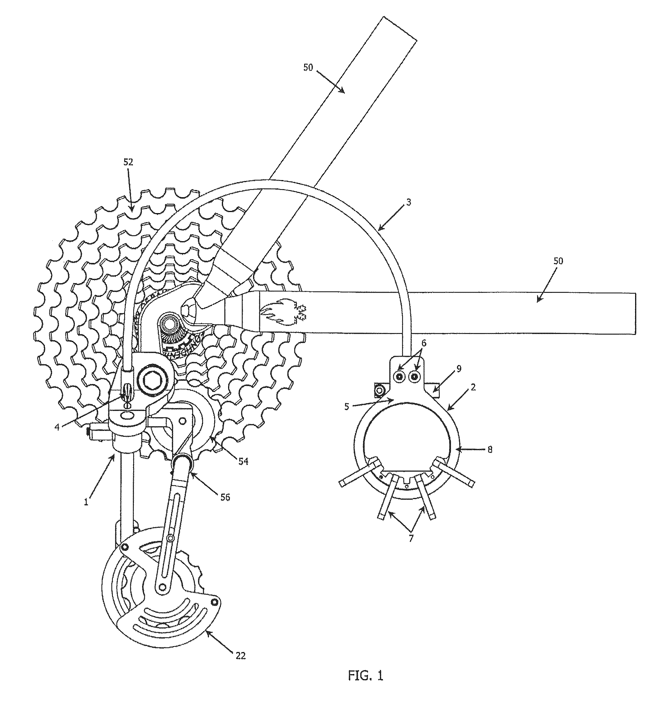
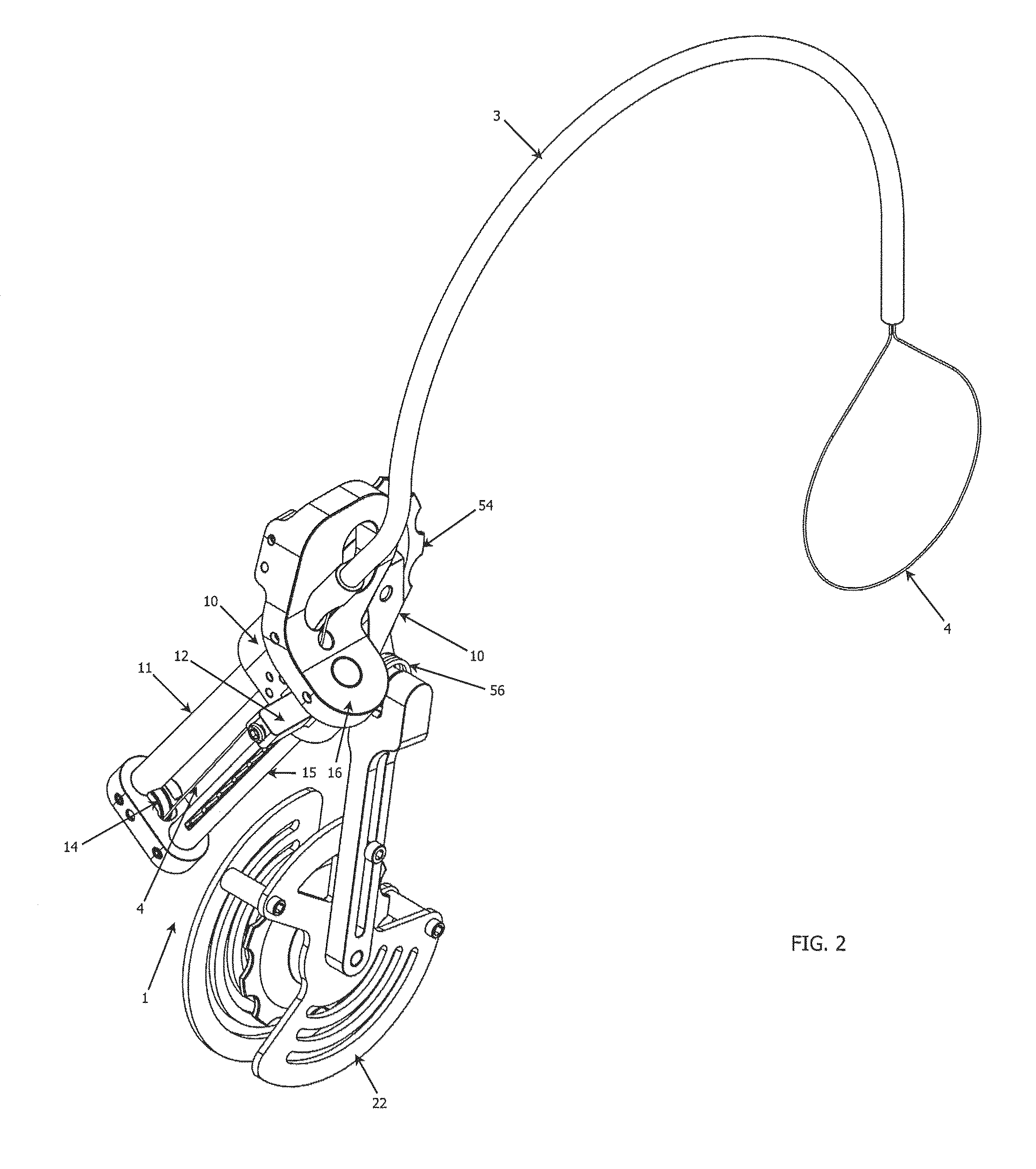
[0008]Embodiments of the present disclosure contemplate an improved gear transmission and derailleur system. For the purposes of the present disclosure, various embodiments may be referred to as the “InGear Transmission System” or the “InGear.” The present disclosure provides a transmission system for bicycles that is more accurate, more efficient, removes the cable slack issue common to prior art designs and provides a derailleur system that reduces or eliminates the need to be tuned. In various embodiments, the InGear Transmission utilizes a user-interfacing control system, or “Cuff-Link” controller to operate a derailleur with ease of shifting. In various embodiments, the derailleur system may be referred to as the “Line Drive” or “Line Drive Derailleur.”
[0009]The InGear system aligns a chain with the center of each sprocket. The Cuff-Link control is mounted to the handlebars and functions by pulling a wire back and forth. This actuation motion may be referred to herein as the “Pull-Pull” design. The Cuff-Link control comprises a pulley or similar feature that does not rely on indexing. Rather, the system pulls a cable back and forth to translate derailleur features from one gear to another. When the Cuff-Link control is connected to the derailleur of the present disclosure through a known cable, the Cuff-Link control is able to pull the derailleur back and forth along its entire track without the need for a large spring.

Problems solved by technology

Not only does this create a bulky, heavy and expensive shifter, but it also requires this added bulk to be mounted to handlebars, where aerodynamics are of concern.
A significant problem with these prior art designs is that the cable is always under tension and as a result, the cable has the ability and tendency to stretch.
When cable stretch occurs, which is common, the derailleur falls out of alignment with the sprockets, creating an undesirable shift, lowering efficiency, and in many cases, preventing the derailleur from shifting to the desired gear entirely.
It is also difficult for prior art designs to perfectly align the derailleur with each sprocket due to the aforementioned cable slack issue as well as the fact that the prior art device used to regulate the accuracy of the derailleur is located almost two meters away from the system.
Cable slack in prior art designs is such a common problem that the designs have many adjustments incorporated into both the shifter and the derailleur to account for the issue.
In addition, these prior art designs contain a chain slack device that is not only inefficient, but prevents the derailleur from functioning on sprockets that are over 36 teeth.

Method used


Image

  • Gear transmission and derailleur system
  • Gear transmission and derailleur system
  • Gear transmission and derailleur system

Examples


Embodiment Construction

[0074]The present disclosure has significant benefits across a broad spectrum of endeavors. It is the applicant's intent that this specification and the claims appended hereto be accorded a breadth in keeping with the scope and spirit of the disclosure being disclosed despite what might appear to be limiting language imposed by the requirements of referring to the specific examples disclosed. To acquaint persons skilled in the pertinent arts most closely related to the present disclosure, a preferred embodiment of the method that illustrates the best mode now contemplated for putting the disclosure into practice is described herein by, and with reference to, the annexed drawings that form a part of the specification. The exemplary method is described in detail without attempting to describe all of the various forms and modifications in which the disclosure might be embodied. As such, the embodiments described herein are illustrative, and as will become apparent to those skilled in t...


PUM


Abstract

A transmission system for vehicles, including bicycles, is disclosed. The system aligns a chain or other drive means to a center of each of a plurality of provided sprockets, allows for a smaller, lighter and more durable shifter / controller, and reduces various complications associated with cable slack and shifting. A derailleur is provided with linear actuated features to directly translate drive means from one position to another along a desired path.

Description

CROSS-REFERENCE TO RELATED APPLICATIONS[0001]This Non-Provisional patent application is a Continuation-in-Part of U.S. patent application Ser. No. 13 / 622,725, filed Sep. 19, 2012, which is a Continuation-in-Part of U.S. patent application Ser. No. 13 / 360,164, filed Jan. 27, 2012, which claims the benefit of priority from U.S. Provisional Patent Application Ser. No. 61 / 484,037, filed May 9, 2011, and U.S. Provisional Patent Application Ser. No. 61 / 437,565, filed Jan. 28, 2011, the entire disclosures of which are hereby incorporated herein by reference.BACKGROUND[0002]Many prior art bike transmission systems use a shifter and derailleur combination that requires the shifter to hold tension on the derailleur by means of a large cable. In these prior art designs, the derailleur is controlled by a single cable from the shifter, requiring the derailleur to incorporate a large spring that is able to pull against the shifter, allowing the shifter to act as if it is pulling the derailleur ba...

Claims


Application Information

Patent Timeline
Patent Type & Authority Patents(United States)
IPC IPC(8): F16H9/00B62K23/04F16H63/00B62K23/06F16H59/00B62M9/124B62M9/1242B62M25/04F16H61/00
CPCB62K23/04B62K23/06B62M9/124B62M9/1242B62M25/04B62M2009/12413
Inventor JOHNSON, LEEMEAGER, BENJAMIN
Owner PAHA DESIGNS
Learn More