Transfer belt mechanism associated with patient transfer gurney system

a technology of transfer belt and patient transfer, which is applied in the field of mechanical equipment used, can solve the problems of patients often having trouble moving themselves from one bed to another, nurses and hospital staff involved in patient transfer are prone to the occupational hazard of lower back pain, and patients are often prone to discomfor

Active Publication Date: 2016-07-19
KONDA VISHWESHWAR REDDY
View PDF12 Cites 5 Cited by
  • Summary
  • Abstract
  • Description
  • Claims
  • Application Information

AI Technical Summary

Benefits of technology

[0011]One of the objectives of the present invention is to provide a mechanism involved in patient transfer apparatus used for transferring invalid patients lying in supine position, from one horizontal surface to another horizontal surface, for e.g.—transferring patients from one bed to another bed, a bed to a stretcher, a bed to an operation theatre table, a bed to an x-ray unit and vice versa in a smooth and stress free manner without lifting the patient.
[0012]One of the objectives of the present invention is to provide a belt that can be easily removed and sterilized before another patient is put on especially for patients with infections.
[0013]One of the objectives of the present invention is to make the transfer less painful and cause less discomfort to the patient back and spine while the patient is loaded or unloaded.

Problems solved by technology

This could be risky and uncomfortable to both the patient and the hospital staff.
Patients often have trouble moving themselves from one bed to another and from one location in a hospital / care facility to another.
Further, in a hospital the nurses and the hospital staff involved in patient transfer are prone to the occupational hazard of lower back ache, which is associated with physical stress experienced while transferring patients.
It has one significant drawback wherein the endless transfer Belt causes a disadvantage during operation.
The disadvantage is that when the top of the belt is moving in one direction, the bottom of the belt moves in the opposite direction.
This makes it difficult for loading the patient onto the patient transfer trolley.
Further the stretcher appears to be heavy and bulky to be handled or to be pushed or moved by the hospital staff.
Replacement of belts is difficult and time consuming.
Further, the leading edge (portion which goes under the patient) will be too thick due to the fact that there are 2 rollers on the leading edge.
This thickness of the leading edge of the stretcher makes the transfer uncomfortable to patients and sometimes even painful.
In case of spinal injury this transfer mechanism can further damage the patient and can even lead to fatal consequences.
In this mechanism replacement of the belt, either for maintenance or for sterilization, is tedious.
Further the mechanism has gears, chains, sprockets which are prone to breakdowns and have maintenance issues.
The gears and chains in the mechanism may require lubrication for smooth operation and therefore not conducive to sterilization.

Method used


Image

  • Transfer belt mechanism associated with patient transfer gurney system
  • Transfer belt mechanism associated with patient transfer gurney system
  • Transfer belt mechanism associated with patient transfer gurney system

Examples


Embodiment Construction

[0034]The best mode for carrying out the invention is presented in terms of its preferred embodiment, herein depicted within the FIG. 1

DETAILED DESCRIPTION OF THE INVENTION

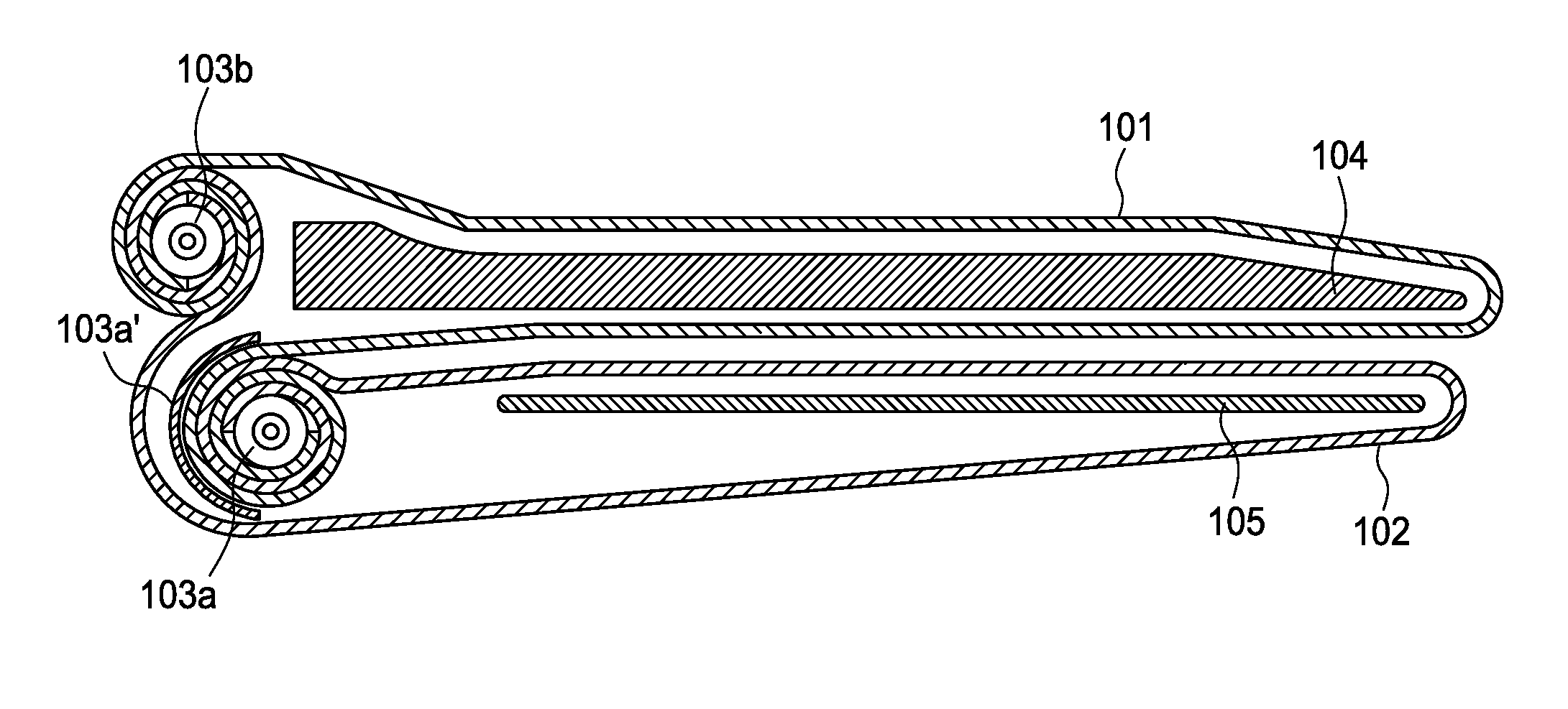
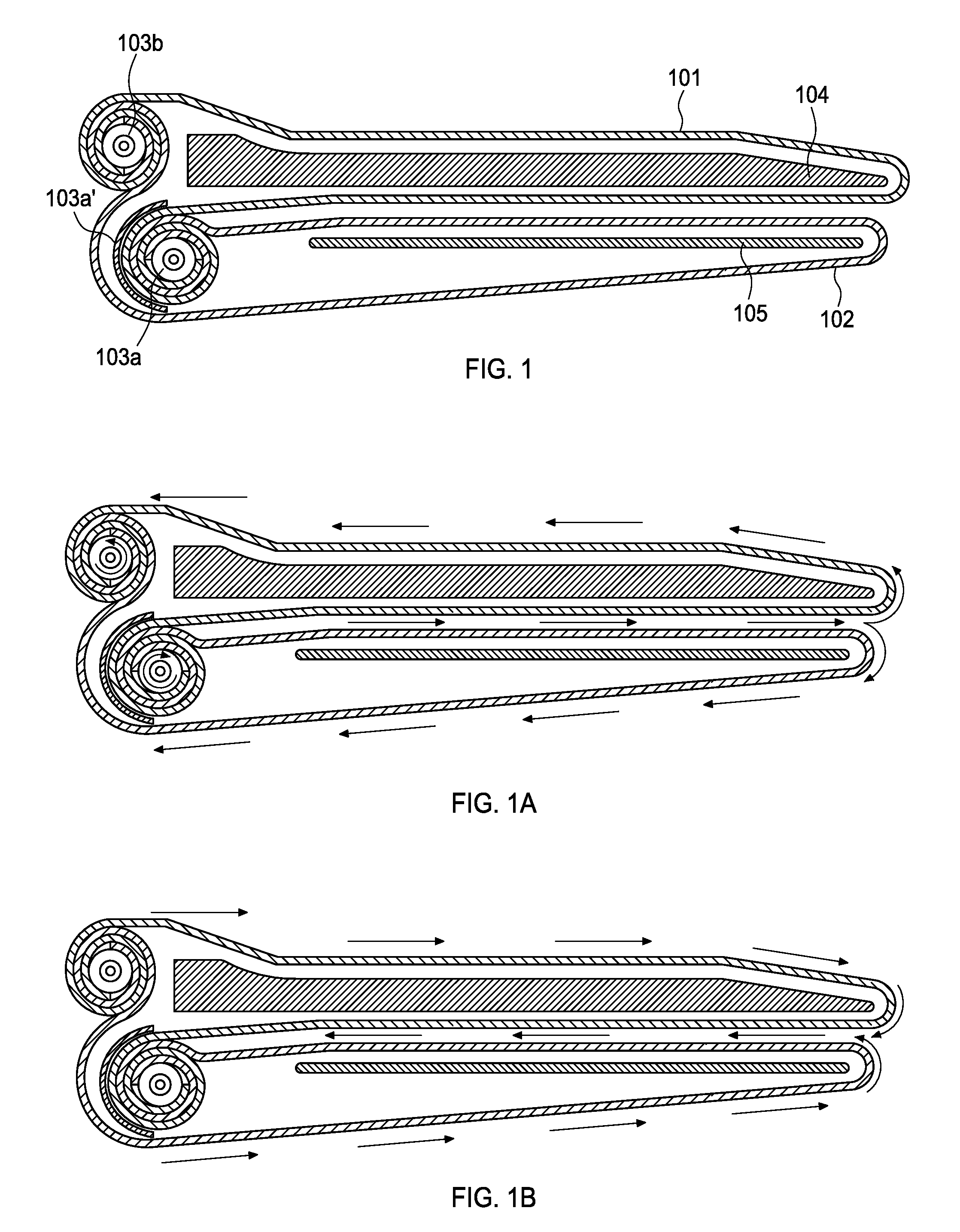
[0035]As shown in FIG. 1, the mechanism includes two flexible non endless belts attached to two rollers, according to the preferred embodiment. In the illustrated embodiment, two flexible non endless belts (101, 102) whose width is slightly less than the length of the stretcher and whose length is slightly longer than thrice the width of the stretcher, wherein said stretcher has two rollers (103a, 103b) on the side where it is mounted on two pillars (not shown in the FIG. 1). One end of first non endless belt 101 also referred as upper belt and one end of second non endless belt 102 referred as lower belt are attached on to roller 103a. The belt 101 or also referred as upper belt goes around the stretcher 104, the belt 102 or also referred as lower belt goes around the Plate 105 below the stretcher and the other e...


PUM


Abstract

The cantilevered stretcher has a transfer belt mechanism which includes two rollers mounted on the side having two flexible non endless belts, where ends of these two flexible non-endless belts attached to one roller and the other ends of these two flexible non-endless belts attached to second roller. Further one belt goes around the stretcher and the other belt goes around the plate below the stretcher. The arrangement of flexible non endless belts moving between the stretcher and plate in same directions, with upper flexible non endless belt going around the stretcher and lower belt going around the plate can be implemented in three and four roller systems. This mechanism can load the patient onto itself in a way that is efficient and easy to operate, thereby making the patient transfer process easier. Further this mechanism is conducive to sterilization, easier to maintain.

Description

CROSS-REFERENCE TO RELATED APPLICATIONS[0001]The present Application is based on Indian Provisional Application No. 1700 / CHE / 2011 filed on May 18, 2011, which in turn corresponds to Indian Application No. 848 / CHE / 2011 filed on Mar. 18, 2011, and priority is hereby claimed under 35 USC §119 based on these applications. Each of these applications are hereby incorporated by reference in their entirety into the present application.TECHNICAL FIELD OF THE INVENTION[0002]The present invention relates to the field of mechanical equipment used in hospitals for transferring patients from one location to another location. More particularly the present invention relates to the transfer belt mechanism used in trolleys, gurneys and stretchers used for transferring patients from one bed to another bed, a bed to operation theatre, a bed to x-ray table and a bed to a stretcher etc.BACKGROUND OF THE INVENTION[0003]A wide variety of patient transfer trolley products have been designed to move patients...

Claims


Application Information

Patent Timeline
Patent Type & Authority Patents(United States)
IPC IPC(8): A61G1/003A61G7/00A61G7/10
CPCA61G7/1019A61G7/1032A61G7/1046
Inventor KONDA, VISHWESHWAR REDDY
Owner KONDA VISHWESHWAR REDDY
Why Eureka
Try Eureka