

Torque converter
- Summary
- Abstract
- Description
- Claims
- Application Information
AI Technical Summary
Benefits of technology
Problems solved by technology
Method used
Image

Examples
first embodiment
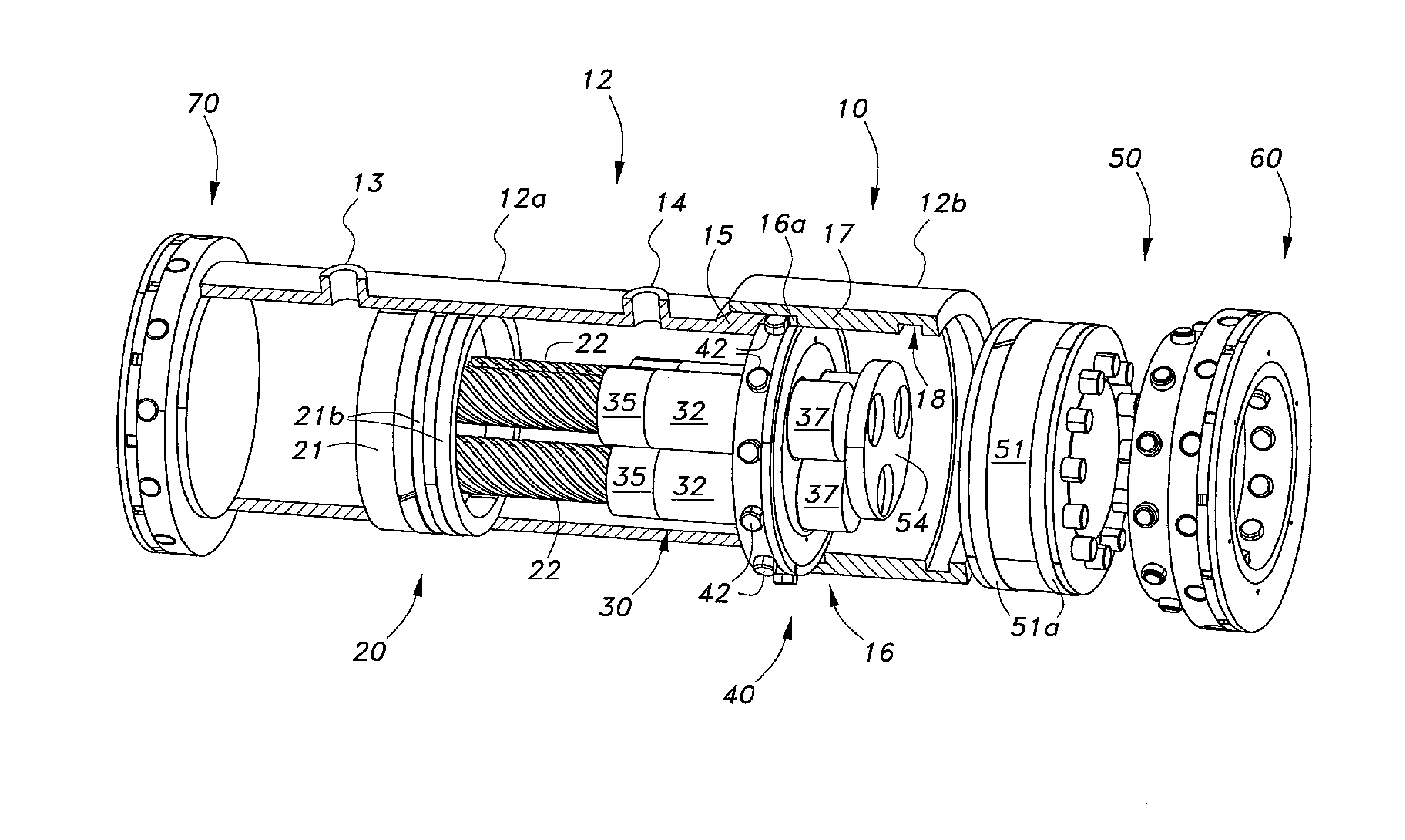
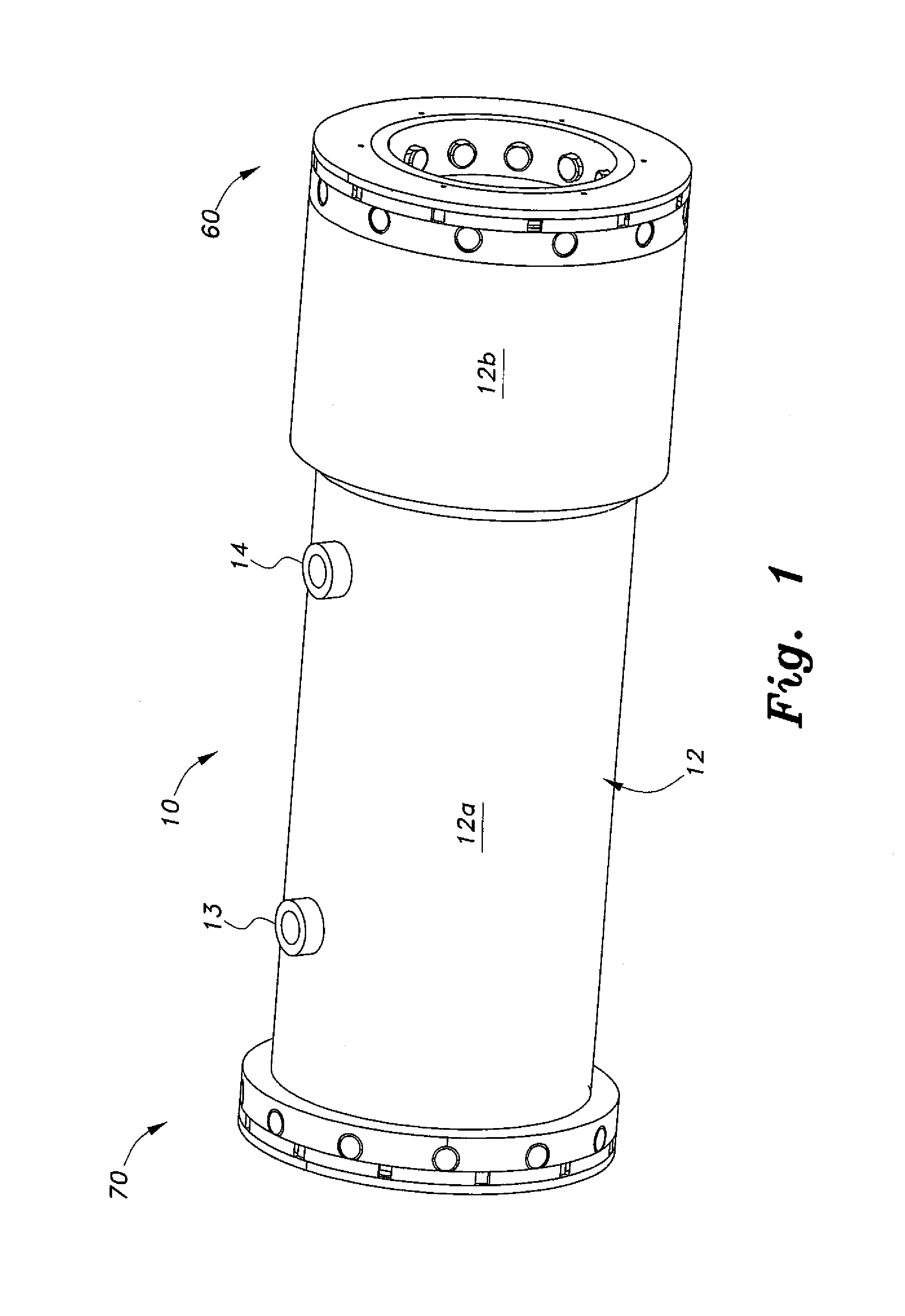
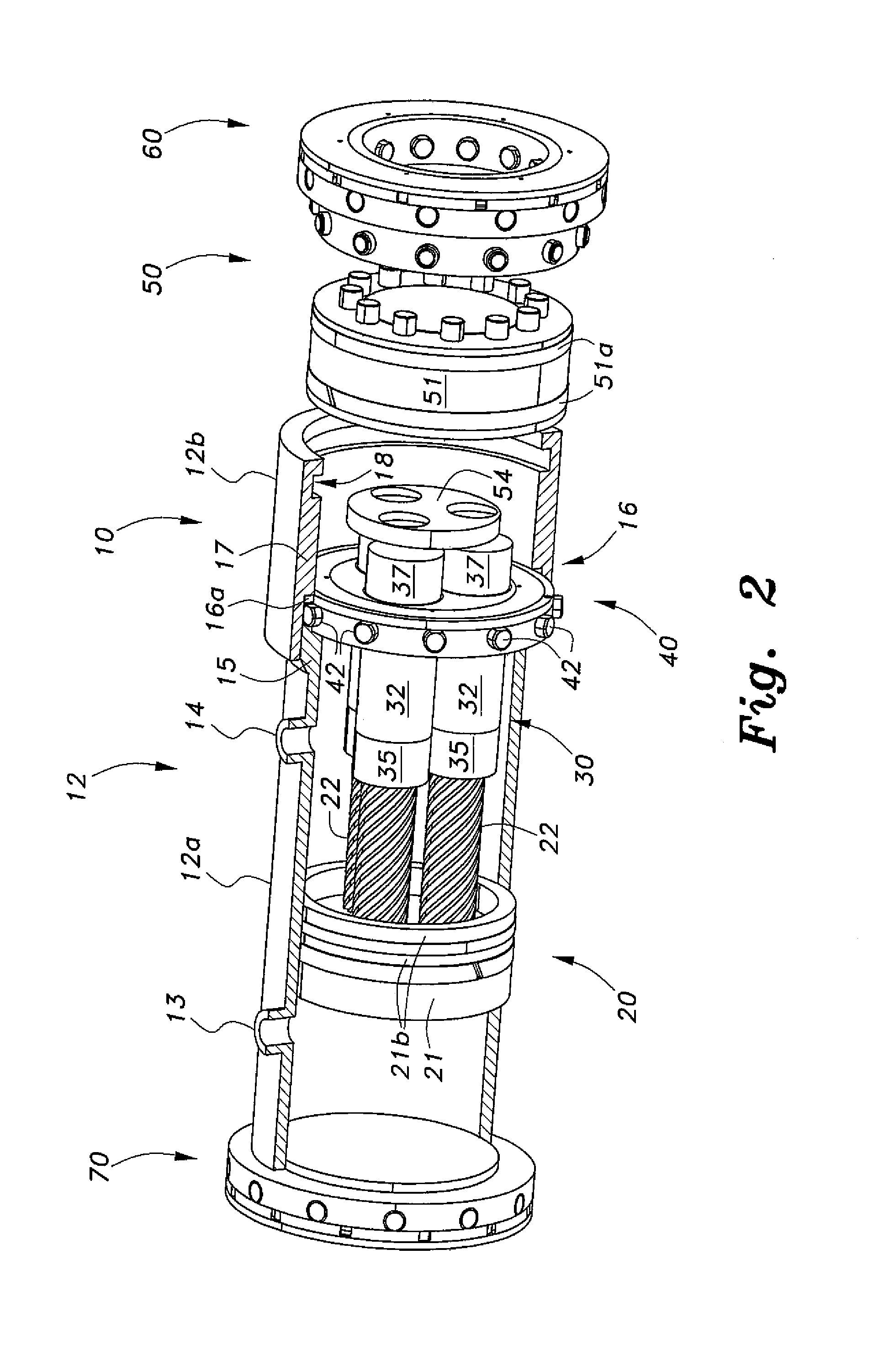
[0022]The torque converter, which is referred to by the reference number 10, generates increased torque by accumulation of a plurality of smaller torque inputs. As best seen in FIGS. 1-4, the torque converter 10 is a type of hydraulic actuator converting linear motion of a reciprocating piston into rotary motion. The torque converter 10 includes a housing 12 having an input end and an opposite output end. A piston assembly 20 is disposed inside the housing 12 and reciprocates therein. The piston assembly 20 engages a helical rotation assembly 30 to convert linear motion of the piston assembly 20 into rotary motion of one or more rotators 31. A torque accumulator 50 is coupled to the rotators 31 to combine the rotary motion of the rotators 31 into total output torque that is substantially the sum of the individual input torques of the rotators 31.
[0023]The housing 12 comprises two parts, a main section 12a and a coaxial collar section 12b. The main section 12a is preferably an elonga...
third embodiment
[0041]a torque converter 200 is shown in FIGS. 8-10. This embodiment is a mechanical version of the previous embodiments where the motive force is provided by mechanical means, rather than hydraulic fluid. Similar components follow a reference numbering scheme similar to the “200” series, as in the previous embodiments, and details thereof have not been set forth for brevity and clarity.
[0042]As shown, the torque converter 200 includes a housing 212 having an input end and an opposite output end. A piston assembly 220 is disposed inside the housing 212 and reciprocates therein. The piston assembly 220 engages a helical rotation assembly 230 to convert linear motion of the piston assembly 220 into rotary motion of one or more rotators 231. A torque accumulator 250 is coupled to the rotators 231 to combine the rotary motion of the rotators 231 into a total output torque that is substantially the sum of the individual input torques of the rotators 231.
[0043]The housing 212 comprises tw...
PUM
 Abstract
Description
Claims
Application Information