Ultrasonic wave motor and ultrasonic wave motor-equipped device

a technology of ultrasonic waves and motors, applied in piezoelectric/electrostriction/magnetostriction machines, mountings, instruments, etc., can solve the problems of difficult to say that the lens holding member can move smoothly, and the complex configuration of the driving device is high cos

Active Publication Date: 2016-07-19
CANON KK
View PDF2 Cites 7 Cited by
  • Summary
  • Abstract
  • Description
  • Claims
  • Application Information

AI Technical Summary

Benefits of technology

[0008]According to an aspect of the present invention, there is provided a driving device having a vibration element, a friction member, and a pressing member for applying pressure in a direction in which the vibration element and the friction member make contact with each other, causing the vibration element and the friction member to make a relative movement by vibration generated in the vibration element. The driving device includes a connection member configured to transmit a driving force caused by the relative movement to a holding member of another member, wherein the holding member makes a movement caused by the transmitted driving force, and a guide member configured to guide the holding member in a moving direction when the vibration element and the friction member make the relative movement. The connection member connects the holding member to the vibration element or the friction member so as not to apply a reaction force caused by the pressing member to the holding member.

Problems solved by technology

However, the driving device discussed in Japanese Patent Application Laid-Open No. 2011-227122 includes rectilinear guide mechanisms for the friction member and the lens holding member, respectively, and thus the driving device is complexly configured of a large number of components at high cost.
Therefore, it is hard to say that the lens holding member can move smoothly.

Method used


Image

  • Ultrasonic wave motor and ultrasonic wave motor-equipped device
  • Ultrasonic wave motor and ultrasonic wave motor-equipped device
  • Ultrasonic wave motor and ultrasonic wave motor-equipped device

Examples


Embodiment Construction

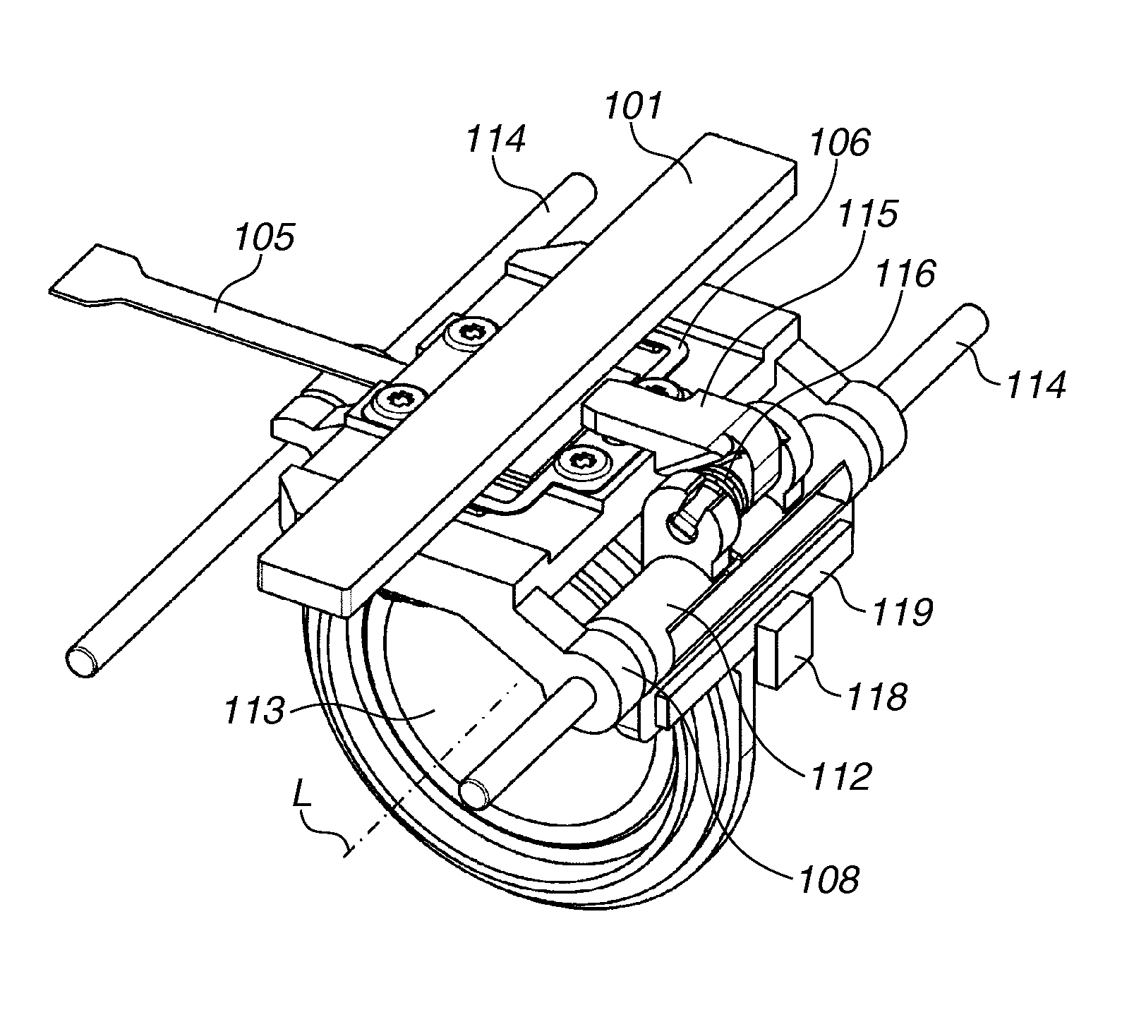
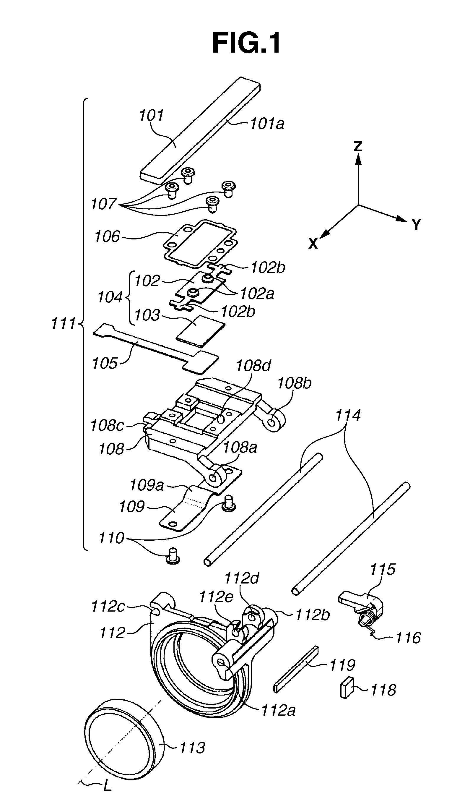
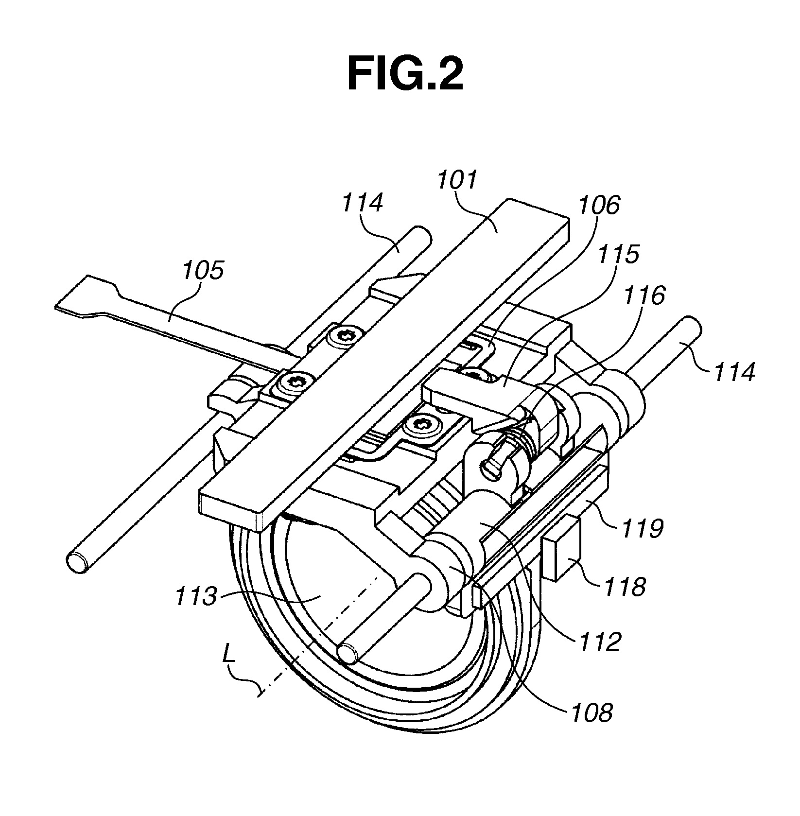
[0014]In an ultrasonic wave motor or an ultrasonic wave motor-equipped device according to an exemplary embodiment of the present invention, when a vibration element and a friction member of the ultrasonic wave motor relatively move rectilinearly, a guide member for a holding member provided for another member is used as a rectilinear guide mechanism. Then, a connection member connects the vibration element or the friction member with the holding member so as not to transmit a reaction force caused by a pressing member to the holding member. Further, a lens holding device according to the present exemplary embodiment includes a guide member held by a lens holding member which is used as a rectilinear guide mechanism of the lens holding member, and a movable frame for holding the vibration element and the pressing member which holds the guide member separately from the lens holding member. For example, because the movable frame, which holds the vibration element and the pressing memb...


PUM


Abstract

A driving device having a vibration element, a friction member, and a pressing member for applying pressure in a direction in which the vibration element and the friction member make contact with each other, causing the vibration element and the friction member to make a relative movement by vibration generated in the vibration element. The device includes a connection member configured to transmit a driving force caused by the relative movement to a holding member of another member, wherein the holding member makes a movement caused by the transmitted driving force, and a guide member configured to guide the holding member in a moving direction when the vibration element and the friction member make the relative movement. The connection member connects the holding member to the vibration element or the friction member so as not to apply a reaction force caused by the pressing member to the holding member.

Description

BACKGROUND OF THE INVENTION[0001]1. Field of the Invention[0002]The present invention relates to an ultrasonic wave motor used for driving a focus mechanism and a zoom mechanism of a lens barrel device, a printer, and a sheet feeding device, an ultrasonic wave motor-equipped device such as the lens barrel device, and a lens holding device.[0003]2. Description of the Related Art[0004]Conventionally, for example, an ultrasonic wave motor has been employed as a driving source of a lens of a camera by taking advantage of its characteristics such as silent operability, low-to-high driving speed capability, and high torque output. A driving device discussed in Japanese Patent Application Laid-Open No. 2011-227122 includes an ultrasonic wave motor configured of a lens holding member for holding a lens, a friction member positioned on the outer side in a radial direction of the lens which is capable of moving in an optical axis direction together with the lens holding member, and a vibratio...

Claims


Application Information

Patent Timeline
Patent Type & Authority Patents(United States)
IPC IPC(8): G02B7/02H02N2/02H02N2/00G02B7/09
CPCH02N2/026G02B7/09H02N2/001G02B7/08
Inventor YAMASAKI, RYO
Owner CANON KK
Why Eureka
Try Eureka