Autostereoscopic display device and driving method

a display device and display device technology, applied in optics, instruments, electrical equipment, etc., can solve the problems of reducing the image resolution as perceived by the viewer, reducing the freedom of viewers in choosing, and simple bar arrangemen

Active Publication Date: 2016-08-02
LEIA INC
View PDF26 Cites 4 Cited by
  • Summary
  • Abstract
  • Description
  • Claims
  • Application Information

AI Technical Summary

Benefits of technology

[0017]An advantage of this approach is that even in the privacy mode, the output brightness to the desired viewing cone is not reduced, and the full display resolution is used.
[0021]In one implementation, the elements provided between the adjacent lenses comprise the polarizer arrangement, and the switchable retarder arrangement is provided before the lens array. In this way, by choosing whether or not to switch the polarization using the retarder, the polarizer elements between the lenses will either perform an absorbing or transmitting function.

Problems solved by technology

A drawback of this type of two-view display design is that the viewer has to be at a fixed position, and can only move approximately 3 cm to the left or right.
The barrier arrangement is simple to produce but is not light efficient.
Increasing the number of views improves the 3D impression but reduces the image resolution as perceived by the viewer, since all views are displayed at the same time by the native display.
The end result is a display with a large viewing angle, although viewers are not entirely free in choosing their location from which to view the 3D monitor or television: at the boundaries between viewing cones the 3D effect is absent and ghost images appear.
This wide viewing angle is a problem in situations where the user of the display would prefer no eavesdropping on all or certain parts of the display content.

Method used


Image

  • Autostereoscopic display device and driving method
  • Autostereoscopic display device and driving method
  • Autostereoscopic display device and driving method

Examples


Embodiment Construction

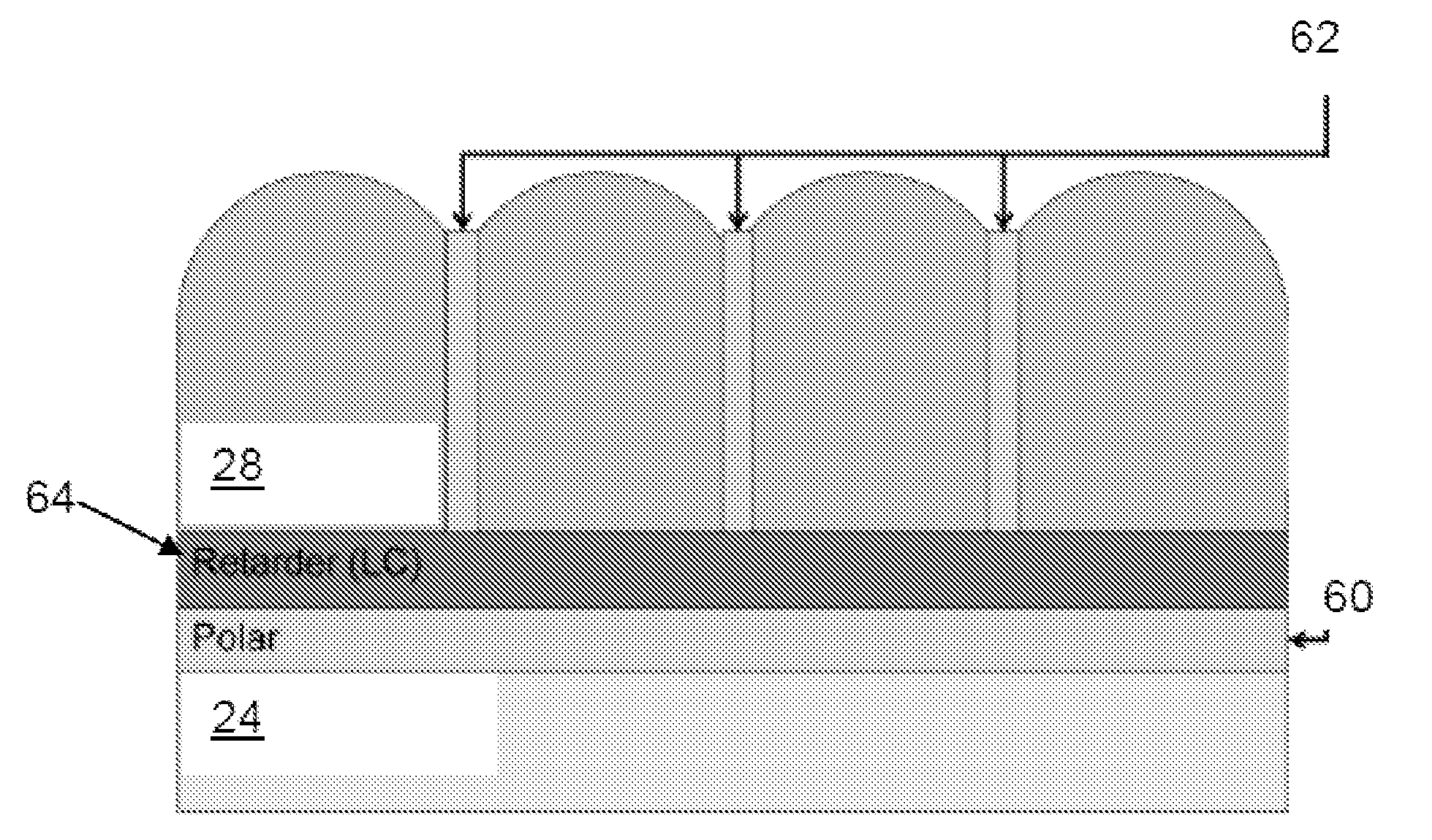
[0048]The invention provides an autostereoscopic display device in which a light blocking arrangement is provided for selectively blocking light which has or would pass between adjacent lenses due to the large lateral (i.e. non-normal) angle of propagation. Elements are provided between adjacent lens locations, and the display can be configured so that light reaching these elements is either allowed to reach the viewer or is blocked from reaching the viewer. This means that a public (multiple cone) viewing mode can be chosen or a private (single narrow viewing cone) viewing mode.

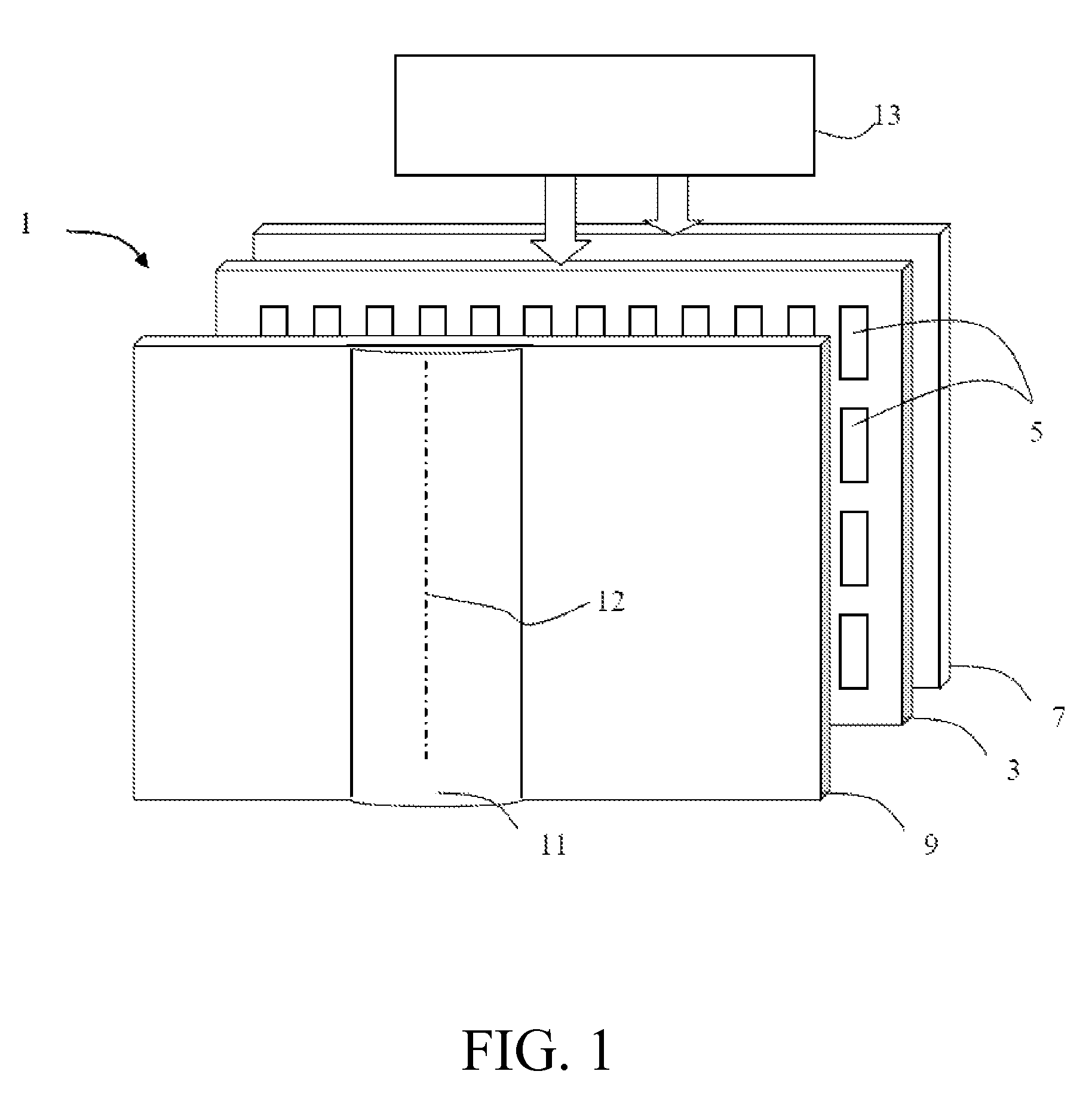
[0049]FIG. 1 is a schematic perspective view of a known direct view autostereoscopic display device 1. The known device 1 comprises a liquid crystal display panel 3 of the active matrix type that acts as a spatial light modulator to produce the display.

[0050]The display panel 3 has an orthogonal array of display pixels 5 arranged in rows and columns. For the sake of clarity, only a small number of display pi...


PUM


Abstract

The invention provides an autostereoscopic display device in which a light blocking arrangement is provided for selectively blocking light which has or would pass between lenses. Elements are provided between adjacent lens locations, and the display can be configured so that light reaching these elements is either allowed to reach the viewer or is blocked from reaching the viewer. This means that a public (multiple cone) viewing mode can be chosen or a private (single narrow viewing cone) viewing mode.

Description

CROSS-REFERENCE TO PRIOR APPLICATION[0001]This application is the U.S. National Phase application under 35 U.S.C. §371 of International Application No. PCT / IB2013 / 054263, filed on May 23, 2013, which claims the benefit of U.S. Provisional Patent Application No. 61 / 654,187, filed on Jun. 1, 2012. These applications are hereby incorporated by reference herein.FIELD OF THE INVENTION[0002]This invention relates to an autostereoscopic display device of the type that comprises a display panel having an array of display pixels for producing a display and an imaging arrangement for directing different views to different spatial positions.BACKGROUND OF THE INVENTION[0003]A first example of an imaging arrangement for use in this type of display is a barrier, for example with slits that are sized and positioned in relation to the underlying pixels of the display. In a two-view design, the viewer is able to perceive a 3D image if his / her head is at a fixed position. The barrier is positioned in...

Claims


Application Information

Patent Timeline
Patent Type & Authority Patents(United States)
IPC IPC(8): G02B27/26H04N13/04G02B27/22G02B30/25G02B30/27G02B30/31
CPCH04N13/0404H04N13/0447G02B27/2214G02B27/26H04N2013/0465H04N13/305H04N13/351H04N2013/405G02B30/31G02B30/27G02B30/25
Inventor KROON, BART
Owner LEIA INC
Why Eureka
Try Eureka