Protocol management method for a passive RF identification device which can harvest power from different power sources

Active Publication Date: 2016-08-09
EM MICROELECTRONIC-MARIN
View PDF2 Cites 29 Cited by
  • Summary
  • Abstract
  • Description
  • Claims
  • Application Information

AI Technical Summary

Benefits of technology

The present invention is about a new protocol management method for a passive RF identification device, which helps to avoid communication protocols from staying in an indefinite state or intermediate state when the reception of an interrogation field is interrupted during a communication protocol. This method allows for a quick restart of the concerned communication protocol without the need for a POR signal of the RF identification device. It also helps to avoid the need for a new execution of the communication protocol when the reader provides its interrogation field. Overall, this method improves the efficiency and reliability of the RF identification device.

Problems solved by technology

In the frame of development of a new RFID product, the inventors have brought out a main problem with respect to the above mentioned transponder of the prior art.
However, such a classical procedure will have no effect on the first communication protocol which remains in an intermediate state so that the first communication protocol will not be driven in its initial state allowing a new execution of this protocol.
This can be problematic because such a new execution will still be done with the old UHF protocol configuration, the transponder having not being reset and reconfigured after a succession of a power-down step and a power-up step triggering the POR function.

Method used


Image

  • Protocol management method for a passive RF identification device which can harvest power from different power sources
  • Protocol management method for a passive RF identification device which can harvest power from different power sources
  • Protocol management method for a passive RF identification device which can harvest power from different power sources

Examples


Embodiment Construction

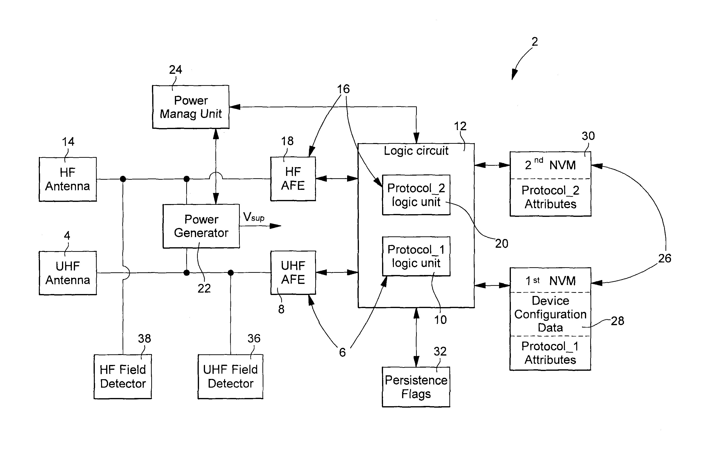
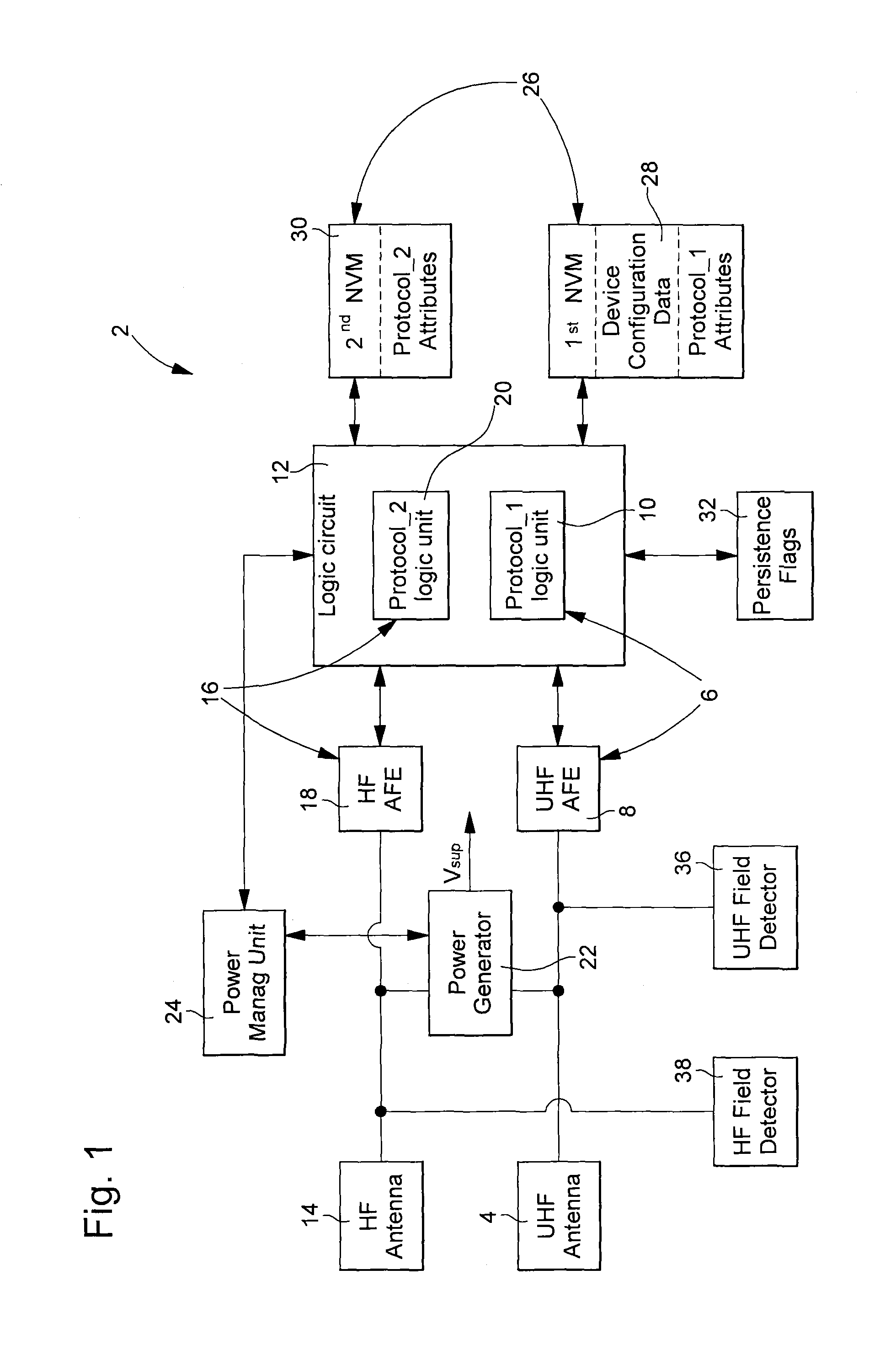
[0023]With reference to FIG. 1, a passive HF-UHF identification device 2 arranged for allowing the implementation of the protocol management method of the invention will be first described. This identification device 2 comprises an UHF antenna 4 for receiving an UHF electromagnetic field, an UHF interface 6 formed by an UHF analog front end 8 (UHF AFE) and an UHF logic unit 10 (Protocol_1 logic unit) which is part of the global logic circuit 12. The device 2 also comprises an HF antenna 14 for receiving an HF electromagnetic field, an HF interface 16 formed by an HF analog front end 18 (HF AFE) and an HF logic unit 20 (Protocol_2 logic unit) which is also part of the logic circuit 12. The device 2 further comprises non-volatile memory means 26, device reset means supported by the logic circuit 12, a power generator 22 providing a supply voltage Vsup and a power management unit 24. The UHF interface is arranged for carrying out an UHF protocol (Protocol_1) and the HF Interface is arr...


PUM


Abstract

The protocol management method concerns a RFID transponder which comprises first and second field detectors respectively for first and second interrogation fields in order to watch for the reception of these first or second interrogation fields at least respectively during executions of corresponding first and second communication protocols. If during the execution of a communication protocol the reception of the corresponding interrogation field is no more detected by the corresponding field detector while the power provided by the power generator remains equal or superior to the requested power level, then this communication protocol is stopped and the RFID transponder enters a Standby state. When the transponder is in this Standby state, the corresponding field detector continues to watch for the reception of the corresponding interrogation field in order to detect if it is again received and, if this is the case, to trigger a restart of this corresponding communication protocol.

Description

FIELD OF THE INVENTION[0001]The present invention concerns a protocol management method for a passive RF identification device (RFID) which is arranged for harvesting power from at least a first reader sending a first interrogation field at a first frequency and from an independent second reader sending a second interrogation field at a second frequency different from the first frequency. Such a device is also named RFID transponder or RFID tag and can be incorporated in a card or in any other portable device, e.g. a wristwatch.[0002]In particular, the identification device has a first interface arranged to carry out a first communication protocol with the first reader and a second interface to carry out a second communication protocol with the second reader. Further, the identification device comprises a power generator arranged for allowing the second reader to partially or fully power supply this identification device while the first interface is in an active state and the first ...

Claims


Application Information

Patent Timeline
IPC IPC(8): G06K7/10
CPCG06K7/10158G06K19/0709
Inventor MAREK, TOMASBICAK, JANKOLMAN, JIRIBILY, PETR
Owner EM MICROELECTRONIC-MARIN
Why Eureka
Try Eureka