
Packing box for display

a packaging box and display technology, applied in the field of packaging boxes, can solve the problems of high labor costs, long hours, and difficult to draw the eye of consumers on the items

Active Publication Date: 2016-09-06
CJ CHEILJEDANG CORP
View PDF14 Cites 0 Cited by
  • Summary
  • Abstract
  • Description
  • Claims
  • Application Information

AI Technical Summary

Benefits of technology

[0014]Accordingly, the present invention has been made in view of the above-mentioned problems occurring in the prior art, and it is an object of the present invention to provide a packing box for display that is capable of removing many inconveniences and the consumption of time and labor cost caused by opening the packing box, drawing items from the packing box, and displaying the items.
[0015]It is another object of the present invention to provide a packing box for display that is capable of removing many problems that items are not fully exposed to the outside even if an open portion is formed on the packing box through the cutting along a cutting line, the items disposed in the packing box are not stably supported and easily fall down, and the inner surfaces of the packing box are brought into contact with the items to make it hard to draw the items from the packing box.

Problems solved by technology

When the items are packed with the packing box, however, they cannot be exposed to the outside, thus making it hard to draw a consumer's eyes on the items.
At this time, the packing box opening work, the item drawing work from the packing box, and the item displaying work are one by one conducted manually, and so as to display a large number of items or large kinds of items in shops, accordingly, long hours and high labor cost should be required.
In case of the packing box A′ having the cutting line 60 formed thereon, however, even if the open portion is formed on the packing box A′ through the cutting along the cutting line 60, the items are not fully exposed to the outside, and further, the items disposed in the packing box A′ are not stably supported and easily fall down.
Furthermore, the inner surfaces of the packing box A′ are brought into contact with the items, thus making it hard to draw the items from the packing box A′.
Accordingly, various endeavors have been made to develop a new packing box capable of maximizing the exposure of items disposed therein, preventing the items disposed therein from falling down, and easily drawing the items from the packing box, but until now, unfortunately, no satisfying results have been suggested.

Method used


Image

  • Packing box for display
  • Packing box for display
  • Packing box for display

Examples


Embodiment Construction

[0036]Hereinafter, an explanation on a packing box for display according to the present invention will be in detail given with reference to the attached drawing.

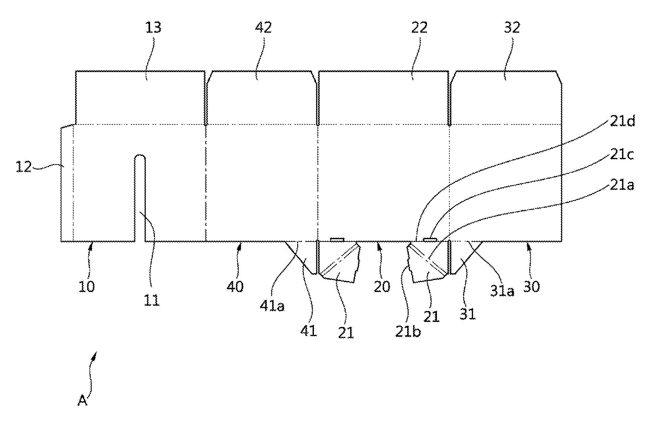
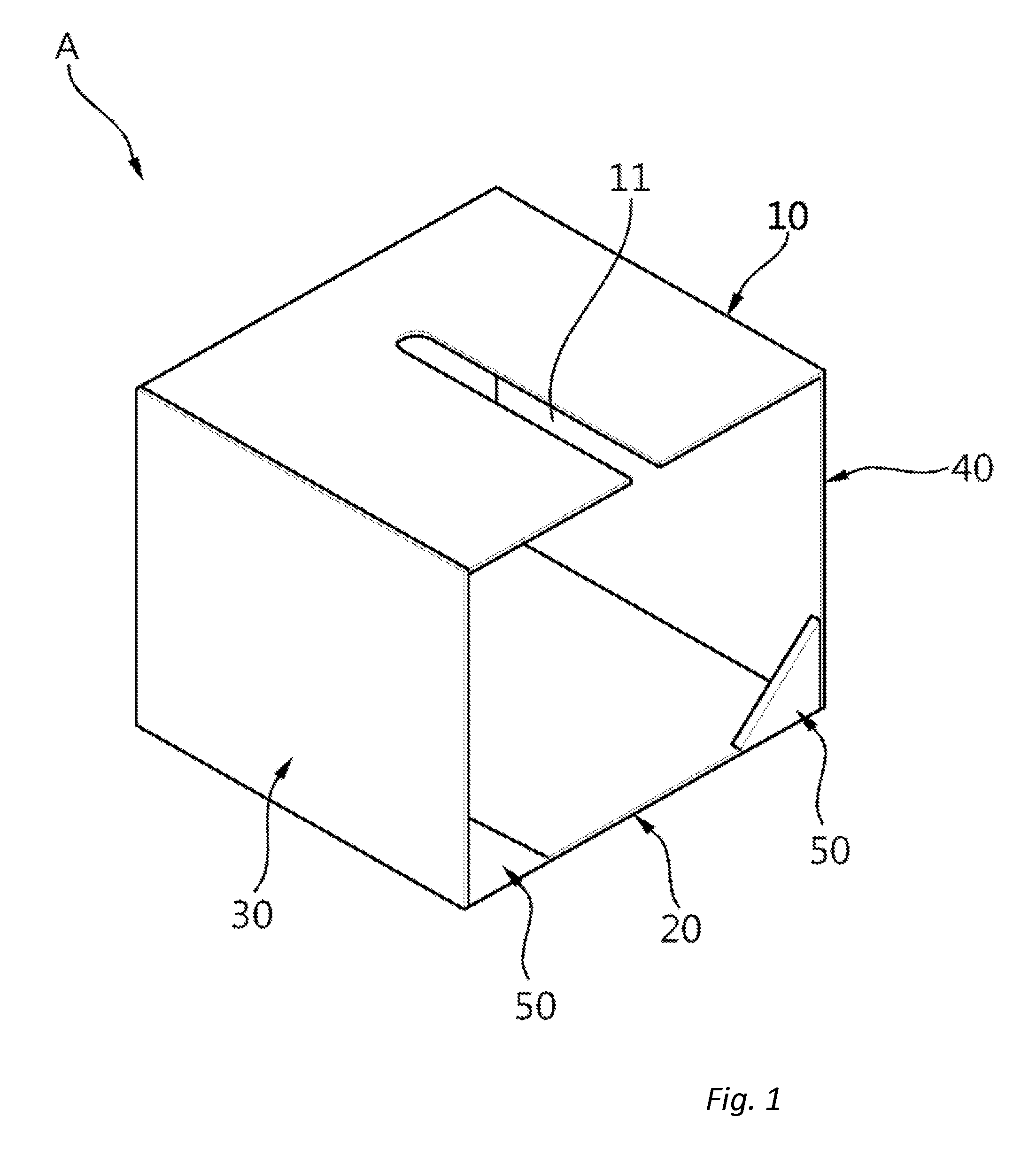
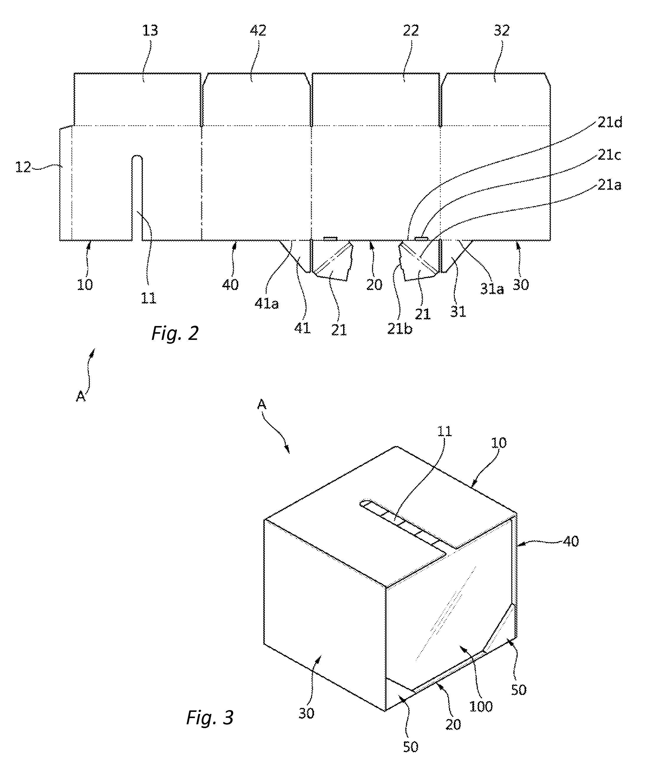
[0037]As shown in FIGS. 1 and 2, a packing box A for display according to the present invention includes a top plate 10, a bottom plate 20, a left plate 30, and a right plate 40.

[0038]The top plate 10 serves to surround the top surfaces of items 100.

[0039]The top plate 10 desirably has a long slot 11 extended backwardly from the intermediate front side end portion in a direction of a width thereof.

[0040]As a result, a user's finger can be inserted under the top plate 11 through the long slot 11 extended backwardly from the intermediate front side end portion in the direction of the width of the top plate 11, thus allowing the items 100 located under the top plate 11 to be easily drawn from the packing box A. In this case, the intermediate front side end portion of the top plate 10 does not mean the right center front side en...


PUM


Abstract

A packing box for display comprising a top plate adapted to surround the top surfaces of items disposed in the packing box; a bottom plate adapted to surround the underside surfaces of the items; a left plate adapted to surround the left surfaces of the items; and a right plate adapted to surround the right surfaces of the items.

Description

RELATED APPLICATIONS[0001]This application claims priority to Korean application 20-2014-0007679 filed on Oct. 22, 2014 and entitled “Packing Box for Display,” the content of which is hereby incorporated by reference in its entirety and for all purposes.BACKGROUND OF THE INVENTION[0002]1. Field of the Invention[0003]The present invention relates to a packing box, and more particularly, to a packing box for display that is open on the front surface thereof to maximize the exposure of items disposed therein, has base parts formed on both sides of the lower end portion of the open front surface thereof to prevent the items disposed therein from falling down, and has a long slot formed on a top plate thereof to easily draw the items therefrom.[0004]2. Background of the Related Art[0005]Small-sized items are generally packed in a given unit.[0006]So as to pack the small-sized items in the given unit, at this time, a packing box made of a corrugated fiberboard is generally used.[0007]If t...

Claims


Application Information

Patent Timeline
Patent Type & Authority Patents(United States)
IPC IPC(8): B65D5/42B65D5/16
CPCB65D5/4204B65D5/16B65D5/52B65D5/70
Inventor PARK, EUN JIN
Owner CJ CHEILJEDANG CORP
Learn More