
Compact proton therapy system with energy selection onboard a rotatable gantry

a proton radiation and gantry technology, applied in the field of medical devices, can solve the problems of reducing the overall cost of such a multi-gantry system, reducing the efficiency of the treatment process, and reducing the cost and space consumption of the system, so as to simplify the proton radiation system, reduce the cost and dimension, and reduce the cost and space consumption

Active Publication Date: 2014-09-18
VARIAN MEDICAL SYSTEMS +1
View PDF1 Cites 29 Cited by
  • Summary
  • Abstract
  • Description
  • Claims
  • Application Information

AI Technical Summary

Benefits of technology

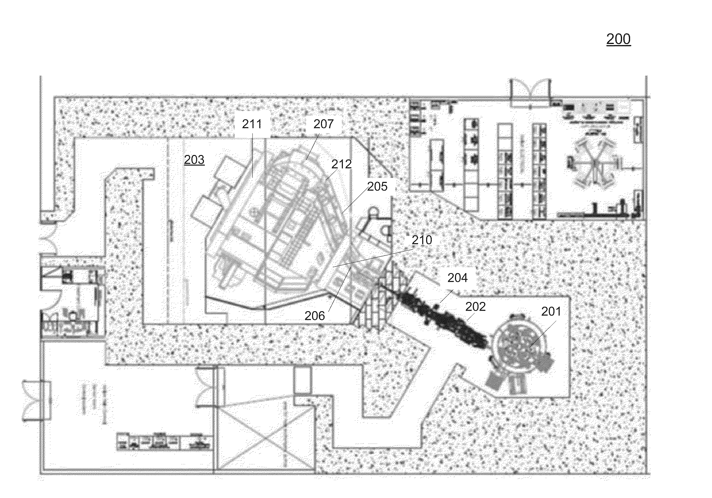
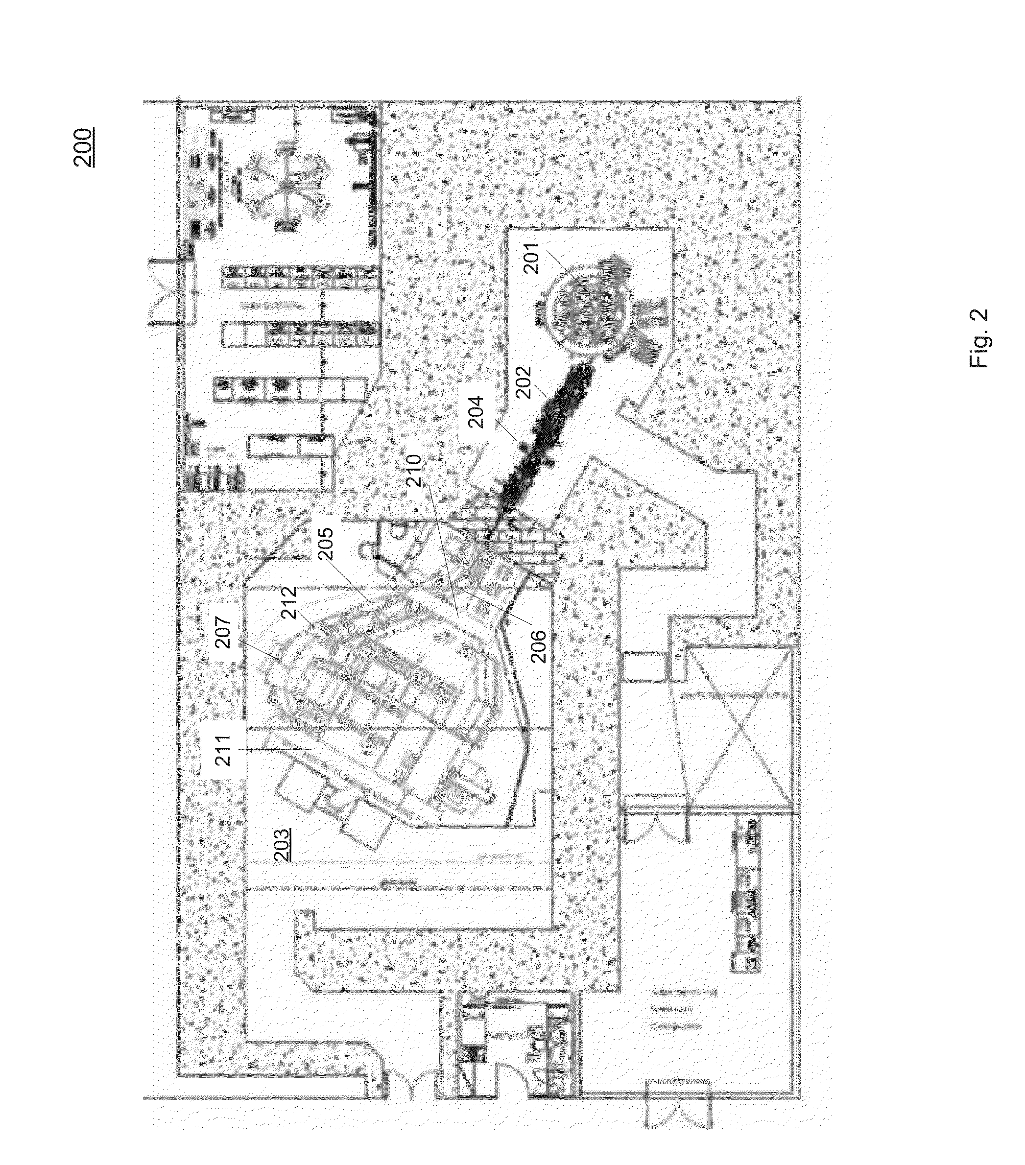
This patent aims to provide a compact proton radiation system with reduced cost and size, suitable for a single-room design. The system utilizes a set of dipole magnets on the gantry for energy selection and particle beam redirecting. Integrating the energy selection magnets onto the gantry decreases the consumption of cost and space, making the system more compact. Another advantage of the system is that it simplifies energy degradation by placing the energy degrader in the atmosphere and replacing the vacuum seal with an air gap at the joint between the stationary portion and the rotating beam line.

Problems solved by technology

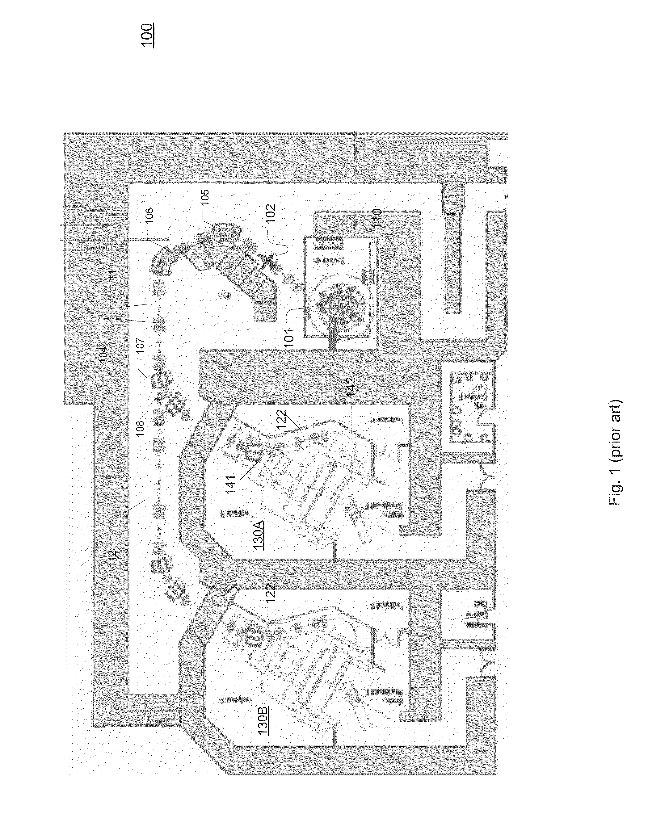
Although using a multi-station single-cyclotron system is effective to distribute the cost for large medical facilities, the overall cost for such a multi-gantry system may be prohibitively high for smaller facilities that may only need one treatment station.
Also, some multi-station systems do not support simultaneous treatment in multiple stations.
This contribute to further disadvantage that a delay at one treatment station can cause delay at the other station.
Among the costly factors in the conventional proton radiation system, the dipole magnets consume significant expenditure associate with manufacture, installation, control, maintenance, and space that is limited and valuable in the medical facility.

Method used


Image

  • Compact proton therapy system with energy selection onboard a rotatable gantry
  • Compact proton therapy system with energy selection onboard a rotatable gantry
  • Compact proton therapy system with energy selection onboard a rotatable gantry

Examples


Embodiment Construction

[0019]Reference will now be made in detail to the preferred embodiments of the present invention, examples of which are illustrated in the accompanying drawings. While the invention will be described in conjunction with the preferred embodiments, it will be understood that they are not intended to limit the invention to these embodiments. On the contrary, the invention is intended to cover alternatives, modifications and equivalents, which may be included within the spirit and scope of the invention as defined by the appended claims. Furthermore, in the following detailed description of embodiments of the present invention, numerous specific details are set forth in order to provide a thorough understanding of the present invention. However, it will be recognized by one of ordinary skill in the art that the present invention may be practiced without these specific details. In other instances, well-known methods, procedures, components, and circuits have not been described in detail ...


PUM


Abstract

Systems and apparatuses for providing particle beams for radiation therapy with a compact design and suitable to a single treatment room. The radiation system comprises a stationary cyclotron coupled to a rotating gantry assembly through a beam line assembly. The system is equipped with a single set of dipole magnets that are installed on the rotating gantry assembly and undertakes the dual functions of beam energy selection and beam deflection. The energy degrader may be exposed to the air pressure. The beam line assembly comprises a rotating segment and a stationary segment that are separated from each other through an intermediate segment that is exposed to an ambient pressure.

Description

CROSS REFERENCE[0001]The present application claims priority to U.S. Provisional Patent Application No. 61 / 798, 354 filed on Mar. 15, 2013. The present disclosure is related to the U.S. patent titled “Irradiation device,” No. 8,053,736, filed on Apr. 5, 2007, which claims priority to German patent application No. 202006019307.3, file don Dec. 21, 2006. The foregoing patent application and patent are hereby incorporated by reference in their entirety for all purposes.TECHNICAL FIELD[0002]Embodiments of the present disclosure relate generally to medical devices, and more particularly, to radiation therapy devices.BACKGROUND[0003]In a typical proton therapy system used for tumor radiation treatments for example, a proton beam is produced in a cyclotron or a synchrotron in a specific level of energy that can be adjusted to a prescribed energy level by virtue of energy selection then provided to a treatment station via a beam transportation system. Such a therapy system includes a partic...

Claims


Application Information

Patent Timeline
Patent Type & Authority Applications(United States)
IPC IPC(8): A61N5/10
CPCA61N5/1077A61N2005/1087A61N2005/1095A61N5/1081A61N2005/109G21K5/04G21K5/08G21K5/10A61N5/103A61N5/1048
Inventor BENNA, MANUELSCHILLO, MICHAELSCHULTHEISS, JURGENCRUZ, LUIS ALBERTO
Owner VARIAN MEDICAL SYSTEMS
Learn More