
Hardness tester

a tester and hardness technology, applied in the field of hardness testers, can solve the problems of inability to generate correct test force, inability to compact the whole tester, and inability to make the horizontal direction of the weight b>203/b> stable, etc., and achieve the effect of accurate test for

Active Publication Date: 2016-09-13
MITUTOYO CORP
View PDF5 Cites 3 Cited by
  • Summary
  • Abstract
  • Description
  • Claims
  • Application Information

AI Technical Summary

Benefits of technology

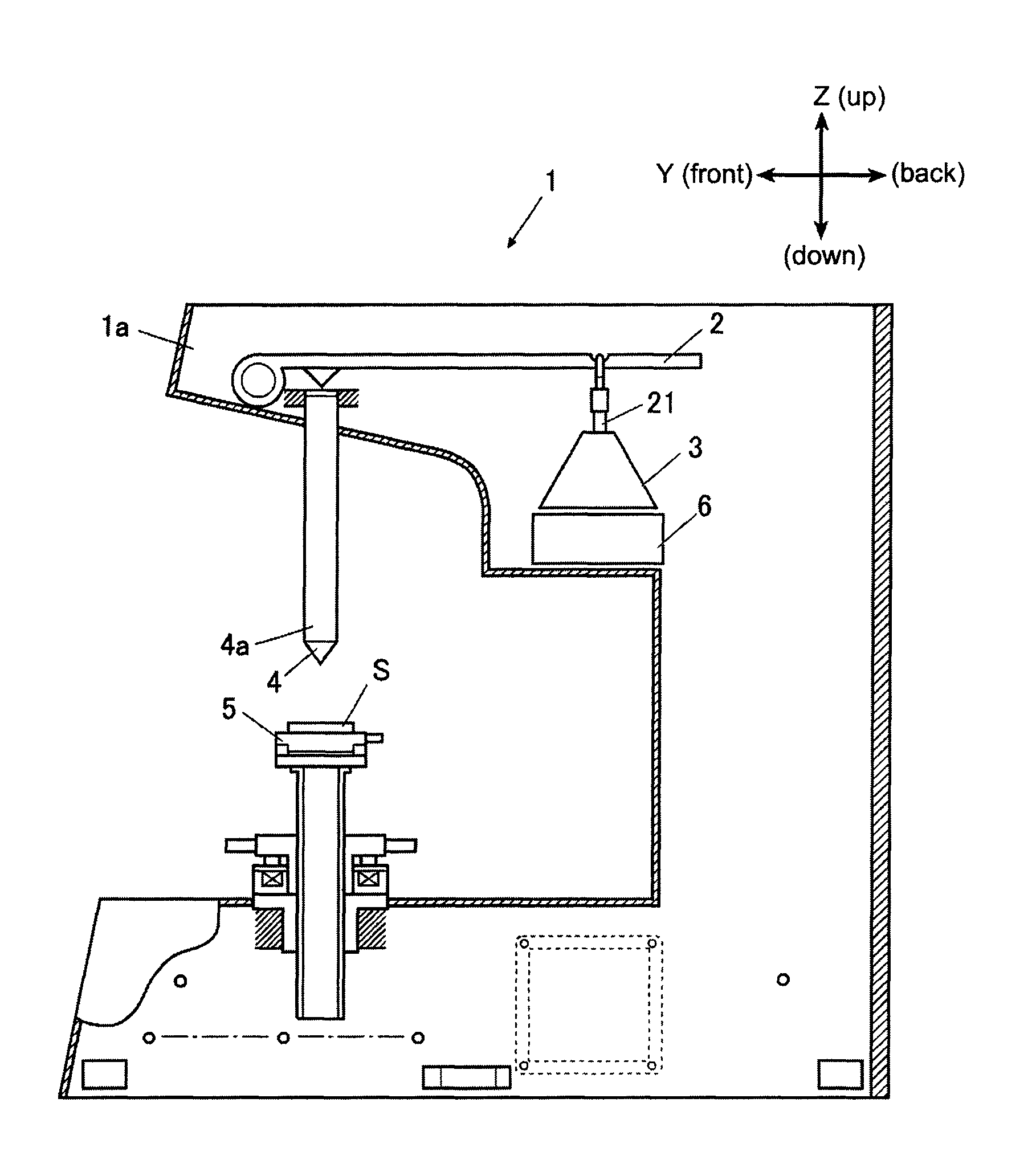
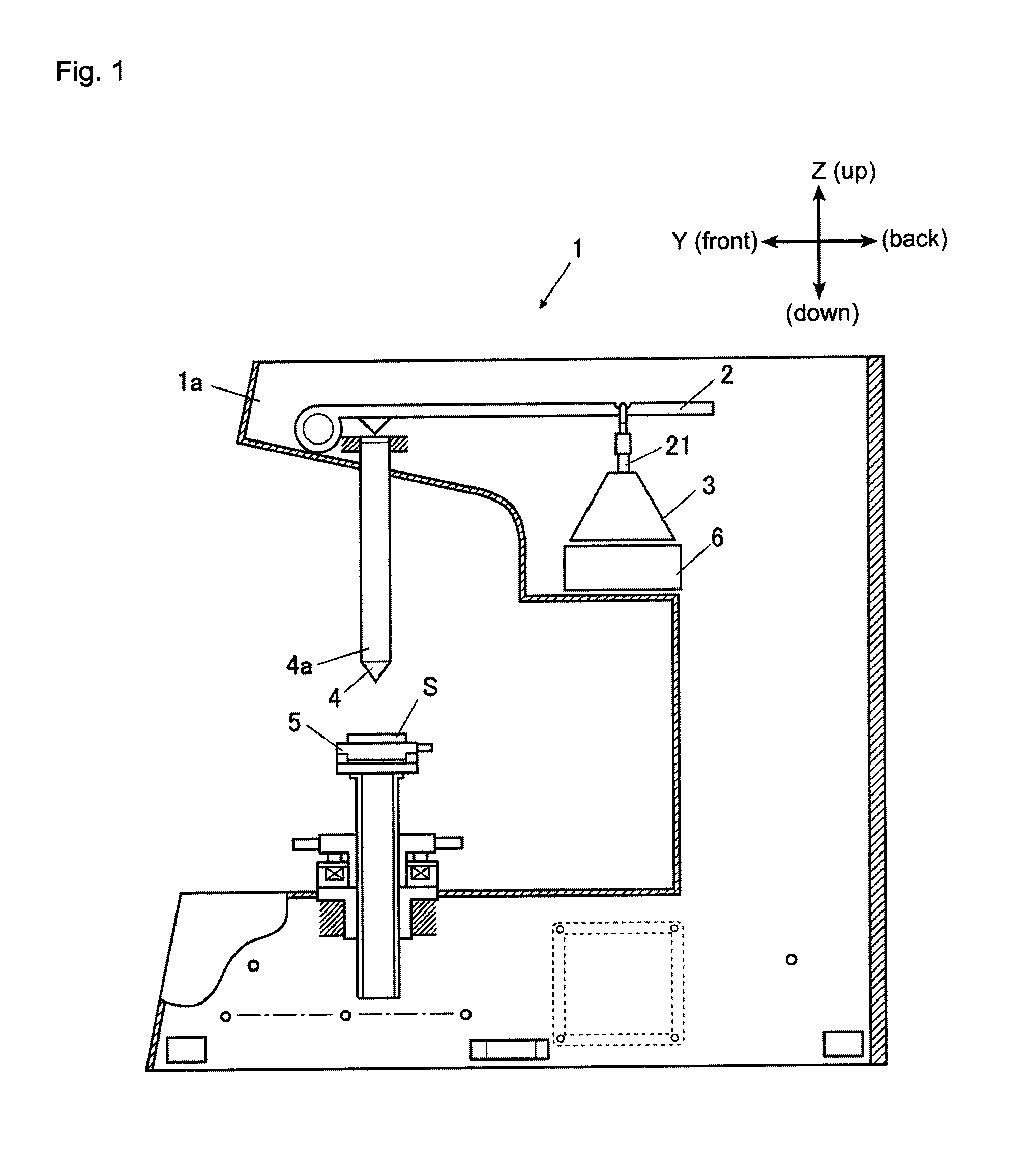
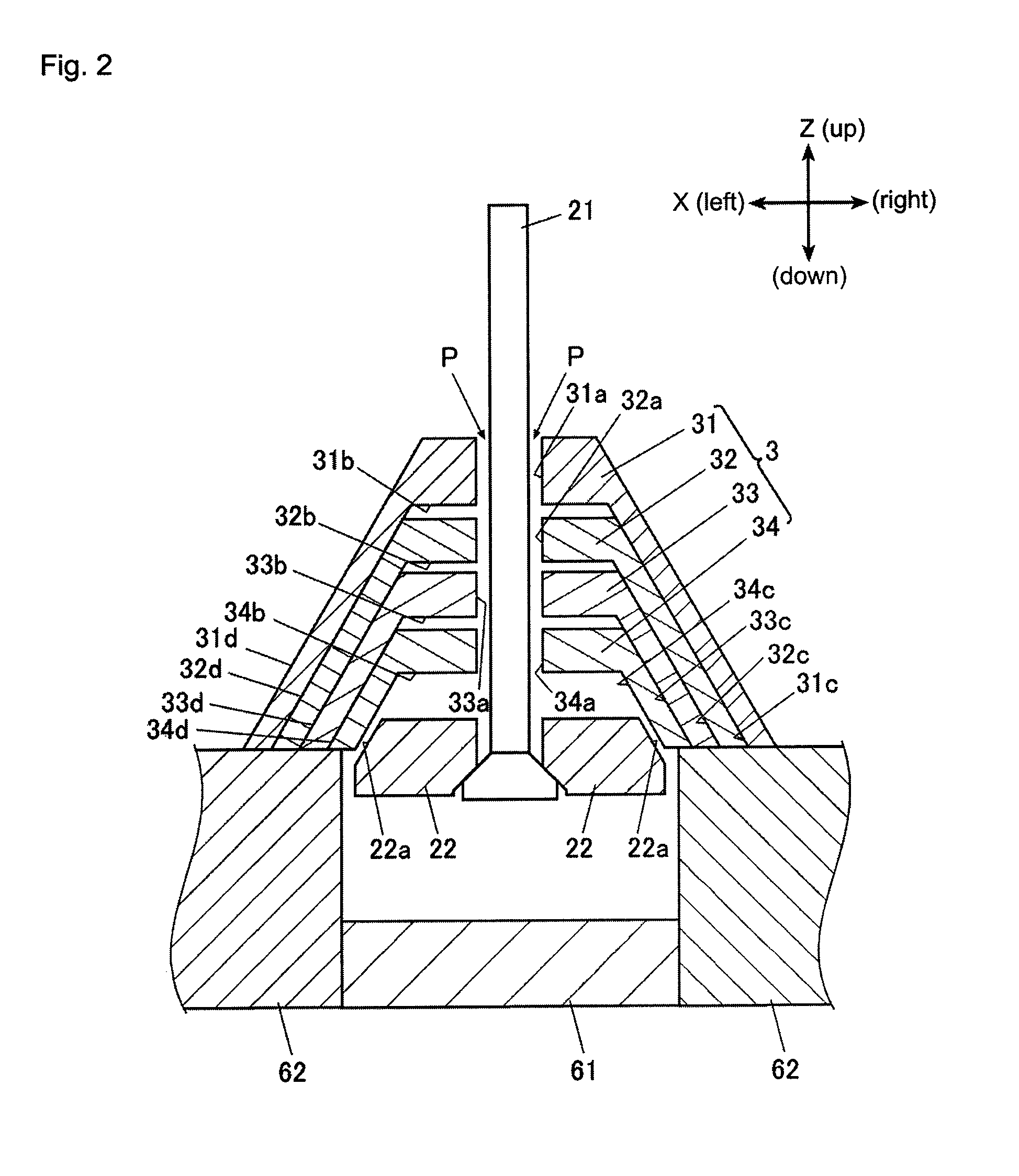
The present invention is a hardness tester that can produce accurate results while keeping the whole tester compact. It achieves this by using a technique where multiple weights can be stacked on top of each other, making them more compact in the vertical direction. The weights also have tapered portions that help regulate horizontal movement and prevent shifting, resulting in an accurate test force.

Problems solved by technology

However, the indenter is a component formed by an expensive material such as diamond and, in order to prevent damaging accidents and the like due to contact with the sample, a large distance must be kept between a tip of the indenter and the sample during standby for a test.
Therefore, there is a problem that the entire tester cannot be made compact.
However, there is a problem that a horizontal-direction position of the weight 203 cannot be made stable.
Therefore, there is a risk that a correct test force may be impossible to generate.

Method used


Image

  • Hardness tester
  • Hardness tester
  • Hardness tester

Examples


example 1

Alternate Example 1

[0044]An example shown in FIG. 8, for example, differs from the embodiment in the shape of the weight 3. In order to simplify the description, identical reference numerals are used for structures similar to those in the embodiment and a detailed description thereof is omitted. Specifically, in the example shown in FIG. 8, a weight 7 has a plurality (three in the present example) of weights 71, 72, and 73 stacked on top of each other in the vertical direction, each of the weights 71, 72, and 73 having a different predetermined weight. The weight 7 is formed so as to have substantially a round columnar shape in a state where each of the weights 71, 72, and 73 are stacked on top of each other. A hollow portion 71a, 72a, and 73a is provided to each of the weights 71, 72, and 73, respectively, the hollow portions 71a, 72a, and 73a running through a horizontal-direction center in the vertical direction. The hollow portions 71a, 72a, and 73a are formed to be wider than t...

example 2

Alternate Example 2

[0045]An example shown in FIGS. 9(A) to 9(C) differs from the embodiment in the structure of the test force switching mechanism 6. In order to simplify the description, identical reference numerals are used for structures similar to those in the embodiment and a detailed description thereof is omitted. Moreover, FIGS. 9(A) to 9(C) are treated as illustrating the weight 3 in a two-dot-dashed line. Specifically, in the example shown in FIGS. 9(A) to 9(C), a test force switching member 8 as a test force switcher is positioned so as to be capable of supporting a bottom end of the plurality of weights 31, 32, 33, and 34. In addition, the test force switching member 8 has a portion of a substantially rectangular shaped plate-shaped member cut away to form a notch 81 and form substantially a “V” shape, as seen in a plan view. The test force switching member 8 is configured to be capable of advance and retreat in a direction (horizontal direction) in which an open end 81a...


PUM

PropertyMeasurementUnit
angleaaaaaaaaaa
hardness testeraaaaaaaaaa
hardnessaaaaaaaaaa

Abstract

The hardness tester includes a plurality of weights; a transmission mechanism transmitting to an indenter a force of gravity acting on the weights; and a test force switching mechanism switching between magnitudes of a test force. The weights include hollow portions running through the weights in a vertical direction; and accommodation portions formed so as to be capable of accommodating the weight directly below. Outside tapered portions are provided to an exterior surface of the weights and inside tapered portions are provided to an interior surface of the accommodation portions. The transmission mechanism includes a shaft member and a weight engagement portion capable of being accommodated by the bottom-most accommodation portion to engage a weight. The weight engagement portion includes a tapered portion engaging the weight to regulate horizontal-direction displacement. A predetermined gap is reserved between the hollow portions and the shaft member.

Description

CROSS-REFERENCE TO RELATED APPLICATIONS[0001]The present application claims priority under 35 U.S.C. §119 of Japanese Application No. 2012-286480, filed on Dec. 28, 2012, the disclosure of which is expressly incorporated by reference herein in its entirety.BACKGROUND OF THE INVENTION[0002]1. Field of the Invention[0003]The present invention relates to a hardness tester.[0004]2. Description of Related Art[0005]Conventionally, a hardness tester (such as a Vickers hardness tester, a Rockwell hardness tester, and the like) is known which measures hardness of a sample by applying a test force to a surface of the sample using an indenter having a planar rhomboid shape or an indenter having a conical or spherical tip to form a polygonal indentation. For example, in a case of a lever-type hardness tester, a weight is used to apply the test force to the surface of the sample.[0006]Specifically, as shown in FIG. 10, in a conventional hardness tester 101, a load lever 102 rotates due to a forc...

Claims


Application Information

Patent Timeline
Patent Type & Authority Patents(United States)
IPC IPC(8): G01N3/42
CPCG01N3/42G01N2203/0033
Inventor KOSHIMIZU, FUMIHIKOSAWA, TAKESHI
Owner MITUTOYO CORP
Learn More