Spring dampened shedding device

Inactive Publication Date: 2006-05-02
DEUTE INST FUR TEXTIL & FASERFORSCHUNG STUTTGART
View PDF2 Cites 11 Cited by
  • Summary
  • Abstract
  • Description
  • Claims
  • Application Information

AI Technical Summary

Benefits of technology

[0008]It is an object of the present invention to provide a loom shedding device in which the retraction spring is anchored in a

Problems solved by technology

The reflections of the mechanical undulation that occur at the contacting points are quantitatively too

Method used


Image

  • Spring dampened shedding device
  • Spring dampened shedding device
  • Spring dampened shedding device

Examples


Embodiment Construction

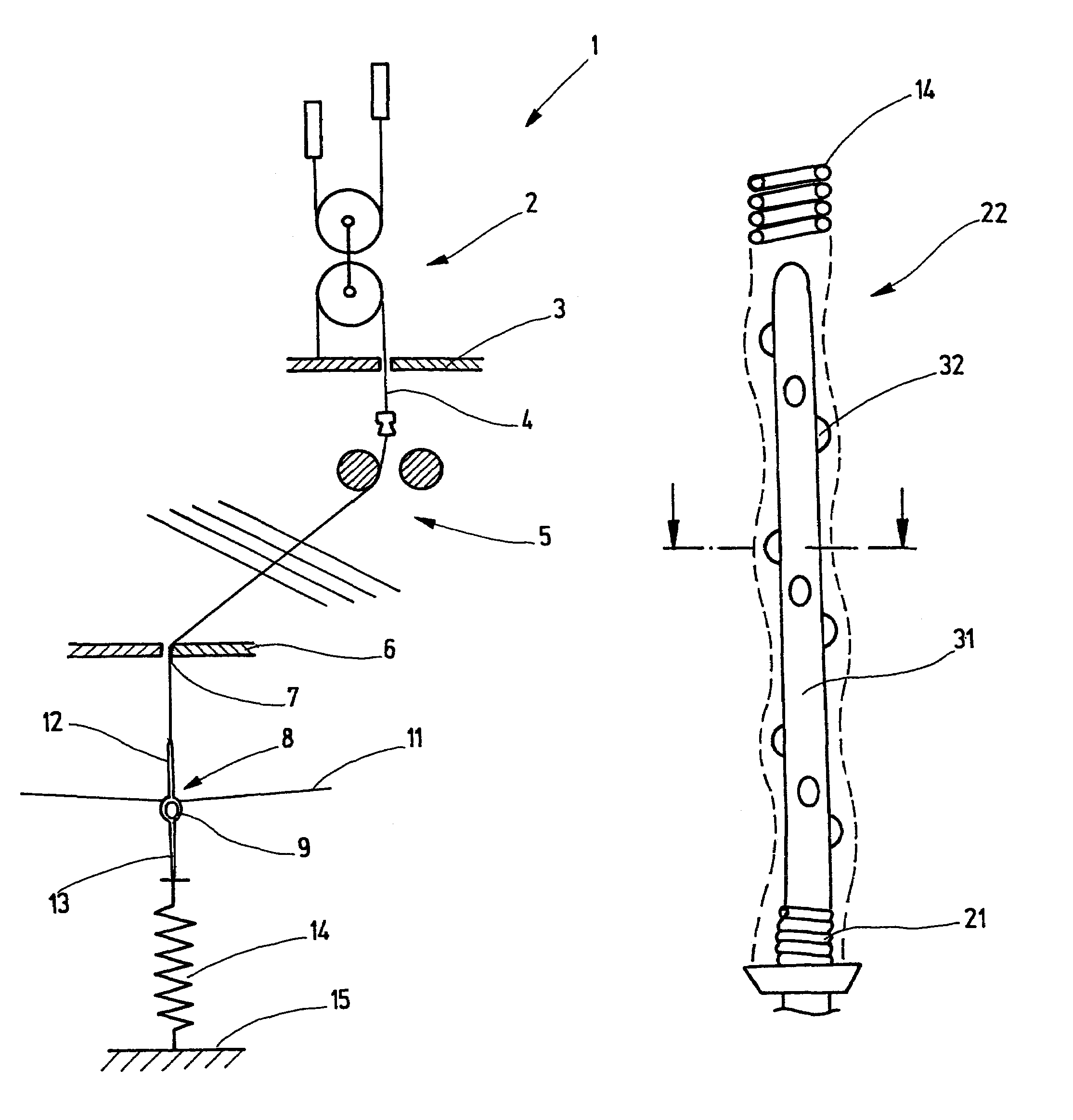
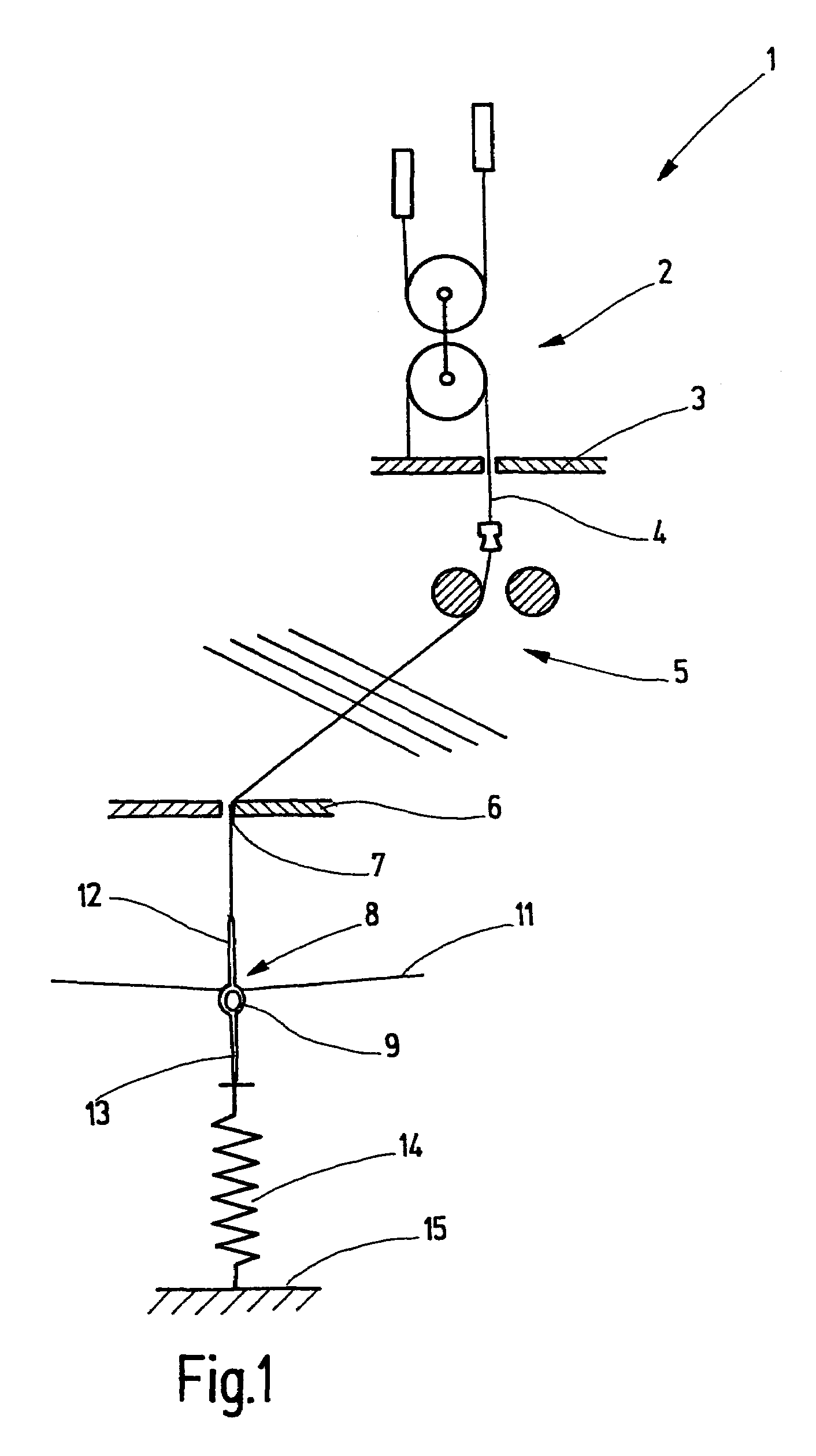
[0034]Referring now more particularly to FIG. 1 of the drawings, there is shown an illustrative shedding device in accordance with the invention in a jacquard loom. The shedding device includes a drive device which includes a roller train 2 as illustrated. From the roller train 2, a collet cord secured to a collet floor 3 extends and changes into a harness cord 4 that passes between a glass grate or a guide floor 5. The harness cord 4 travels on to a harness board 6, where it emerges at the bottom through a bore 7. On the lower end, that is, the end of the harness cord 4 that is remote from the roller train 2, a heddle 8 is secured. The heddle 8 has an eyelet or eye 9 for a warp thread 11. From the eye 9, upper and lower heddle shafts 12, 13 extend, located on the same straight line. The lower end of the lower heddle shaft 13 is connected to a retracting spring 14, which is anchored at 15 to the machine frame or to the floor.

[0035]The motion of the roller train 2 is transmitted to t...


PUM


Abstract

A shedding device in a jacquard loom, having a heddle with a retracting spring rigidly anchored in the loom or to the floor for urging the heddle to a lower shed forming position. To suppress the development of resonance in the spring, a core element is provided, which contacts the inside of the spring at points spaced apart from one another and forces the spring to take a course which deviates from the rectilinear. As a result, friction forces that contribute to damping the spring motion are created between the spring and the core element.

Description

FIELD OF THE INVENTION[0001]The present invention relates generally to weaving looms, and more particularly to a spring controlled drive for reciprocating the heddle of such weaving looms.BACKGROUND OF THE INVENTION[0002]In weaving looms, and particularly in jacquard looms, heddles are moved in one direction while being pulled by a spring in the other direction. Generally, the heddle is moved by the spring to form the lower shed. The spring is anchored at its opposite end in stationary fashion in the loom or to the floor and keeps a harness cord and the heddle under tension during their operation.[0003]Like any spring-elastic system, the assembly comprising the spring, heddle and harness cord also exhibits a resonance phenomena, including the propagation of undulations that pass through the linear system. The natural resonance of the system does not matter, as long as the rate of motion of the heddle is low compared to the resonant frequency. However, at the moment when the rate of ...

Claims


Application Information

Patent Timeline
IPC IPC(8): D03C7/00D03C3/32D03C3/40D03C3/42D03C3/44
CPCD03C3/44D03C3/42
Inventor BAUDER, HANS-JURGENWEINSDORFER, HELMUT
Owner DEUTE INST FUR TEXTIL & FASERFORSCHUNG STUTTGART
Why Eureka
Try Eureka