Control device and control method for internal combustion engine

a control device and internal combustion engine technology, applied in the direction of electric control, machines/engines, mechanical equipment, etc., can solve the problems of insufficient purging, complication of configuration, and inability to introduce evaporated fuel to a portion downstream of the throttle valve, so as to reduce the compression ratio, rapid purging, and rapid purging of evaporated fuel

Active Publication Date: 2016-09-27
NISSAN MOTOR CO LTD
View PDF11 Cites 1 Cited by
  • Summary
  • Abstract
  • Description
  • Claims
  • Application Information

AI Technical Summary

Benefits of technology

[0011]By the increase of the fuel amount and the intake air quantity which are necessary for the identical torque and engine speed in this way, it is possible to introduce more evaporated fuel to the intake system. Accordingly, it is possible to rapidly purge the evaporated fuel by the low frequency or by (during) the short period.
[0012]By the present invention, when the evaporated fuel is accumulated within the evaporation fuel processing device due to the insufficient purge of the evaporation fuel, it is possible to further rapidly purge by decreasing the compression ratio by the variable compression ratio mechanism, and to more surely prevent the outflow of the evaporation fuel to the outside.

Problems solved by technology

Accordingly, in a case where the frequency of the purge is small, it is not possible to sufficiently purge.
In particular, in a case where the internal combustion engine is provided with a turbocharger, in a supercharging (pressure-charging) region in which the pressure becomes the positive pressure, it is not possible to introduce the evaporated fuel to a portion downstream of the throttle valve.
However, this may cause the complication of the configuration.

Method used


Image

  • Control device and control method for internal combustion engine
  • Control device and control method for internal combustion engine
  • Control device and control method for internal combustion engine

Examples


Embodiment Construction

[0017]Hereinafter, one embodiment of the present invention is illustrated in detail based on the drawings.

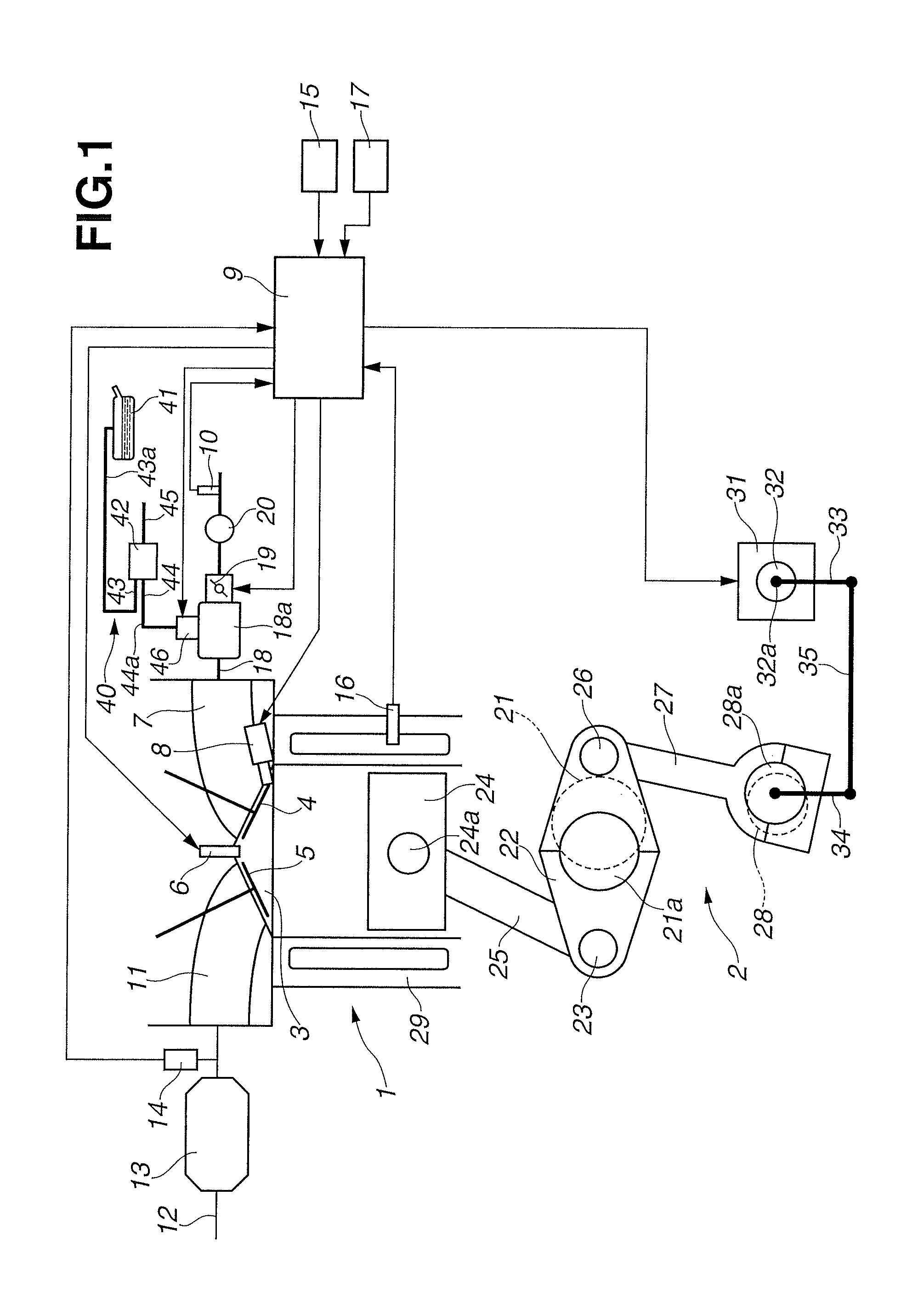
[0018]FIG. 1 shows a system configuration of an internal combustion engine for a vehicle to which the present invention is applied. This internal combustion engine 1 is an in-cylinder direct injection type spark ignition internal combustion engine which is provided with a turbocharger, and a variable compression ratio mechanism 2 which uses, for example, a multi-link type piston crank mechanism. In this internal combustion engine 1, a pair of intake valves 4 and a pair of exhaust valves 5 are disposed on a wall surface of a ceiling (top surface) of a combustion chamber 3. An ignition plug 6 is disposed at a central portion which is surrounded by these intake valves 4 and exhaust valves 5.

[0019]A fuel injection valve 8 is disposed below an intake port 7 which is arranged to be opened and closed by the intake valves 4. The fuel injection valve 8 is arranged to directly inject the ...


PUM


Abstract

A control device for an internal combustion engine provided with an evaporated fuel processing device arranged to temporarily store an evaporated fuel generated in a fuel tank, to purge the evaporated fuel during drive of the engine, and to introduce the evaporated fuel to an intake system, and a variable compression ratio mechanism arranged to vary a mechanical compression ratio, the control device includes: a section configured to sense a state in which the evaporated fuel is accumulated in the evaporated fuel processing device, during a drive of the engine after a warming-up of the internal combustion engine is finished, the control device being arranged to purge the evaporated fuel by decreasing the mechanical compression ratio by the variable compression ratio mechanism when it is sensed that the evaporated fuel is accumulated.

Description

TECHNICAL FIELD[0001]This invention relates to an internal combustion engine provided with an evaporated fuel processing device arranged to temporarily store an evaporated fuel generated in a fuel tank, to purge the evaporated fuel during drive of the engine, and to introduce the evaporated fuel to an intake system, more specifically to a control device and a control method for an internal combustion engine provided with a variable compression ratio mechanism.BACKGROUND ART[0002]For example, a patent document 1 and so on discloses an evaporated fuel processing device arranged to temporarily store an evaporated fuel generated in a fuel tank in a canister and so on, to purge the evaporated fuel during drive of the engine, and to introduce the evaporated fuel to an intake system.[0003]In particular, the patent document 1 relates to the evaporated fuel processing device of the internal combustion engine provided with a turbocharger. The patent document 1 has a configuration including a ...

Claims


Application Information

Patent Timeline
Patent Type & Authority Patents(United States)
IPC IPC(8): F02D41/00F02D41/14F02D15/02F02M25/08F02D23/00F02B75/12
CPCF02D41/004F02D15/02F02D41/0032F02D41/0042F02D41/1486F02M25/089F02M25/0854F02B2075/125F02D23/00F02M25/0818Y02T10/123Y02T10/12
Inventor MANO, TADAKI
Owner NISSAN MOTOR CO LTD
Why Eureka
Try Eureka