Process for manufacturing a hollow body and the manufactured body

a manufacturing process and hollow body technology, applied in mechanical equipment, transportation and packaging, other domestic objects, etc., can solve the problems of similar problems, high cost of machines themselves, and high cost of manufacturing and maintenance operations, so as to reduce the cost of materials

Active Publication Date: 2019-06-25
PLASTIC OMNIUM ADVANCED INNOVATION & RES SA
View PDF25 Cites 0 Cited by
  • Summary
  • Abstract
  • Description
  • Claims
  • Application Information

AI Technical Summary

Benefits of technology

[0020]Advantageously, the multilayer structure of the diesel tank (or filler pipe) according to the invention is composed of material that is distinct from (i.e. that is not) material that is a barrier to liquids and / or gases. In other words, the multilayer structure of the diesel tank (or filler pipe) according to the present invention does not comprise any barrier layer. The material cost of the diesel tank according to the present invention is effectively reduced.
[0041]In a preferred embodiment, the extruder can be purged with a mixture of HDPE and adhesive. Advantageously, the composition of the mixture of HDPE and adhesive can be made such that its viscosity is close to that of the barrier layer (for example, EVOH). This results in a faster purging of the extruder.
[0045]Thus, it is proposed to replace the adhesive layer by a HDPE layer. By this way, the multilayer parison from which the diesel tank / filler pipe according to the present invention is manufactured can be made of thermoplastic layers only (i.e. no barrier layer and no adhesive layer). As a result, pure plastic diesel tank / filler pipe can be manufactured. The fact to replace the adhesive layer by a HDPE layer allows reducing the material cost of the diesel tank / filler pipe.
[0047]For example, the amount of adhesive extruded during the second period of time (i.e. period for manufacturing diesel tank / filler pipe) can be reduced up to 80% as compared to the amount of adhesive extruded during the first period of time (i.e. period for manufacturing gasoline tank / filler pipe). This allows reducing the material cost of the diesel tank / filler pipe.

Problems solved by technology

It is to note that similar problems are encountered in the case of the production of diesel filler pipes and gasoline filler pipes for motor vehicles.
The major drawback of using two distinct machines is that it is expensive and cumbersome.
Not only the cost of the machines themselves is expensive, but also the cost related to the manufacturing and maintenance operations.
In certain situation, the installation of two distinct machines at the same production site is not possible due to lack of space.

Method used


Image

  • Process for manufacturing a hollow body and the manufactured body
  • Process for manufacturing a hollow body and the manufactured body
  • Process for manufacturing a hollow body and the manufactured body

Examples


Embodiment Construction

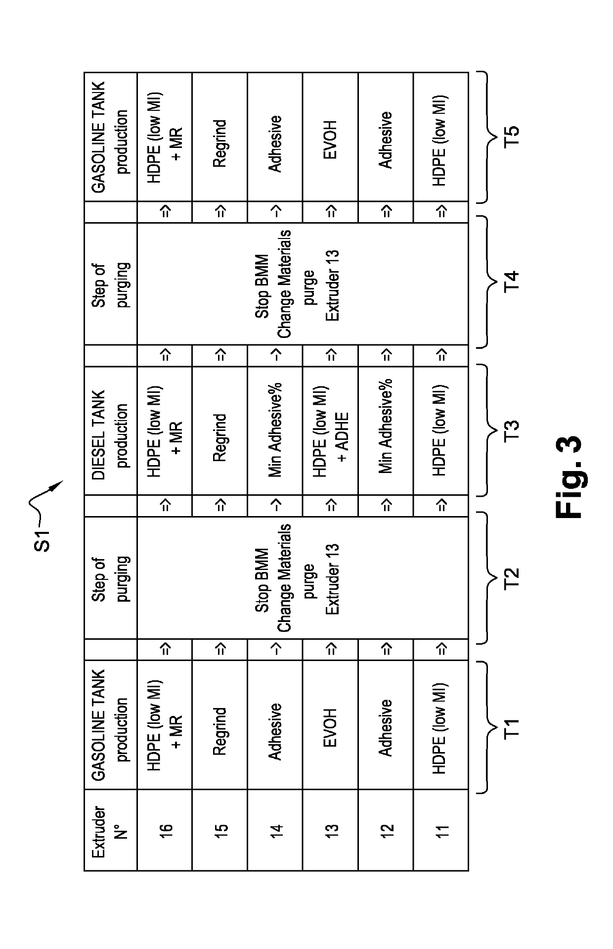
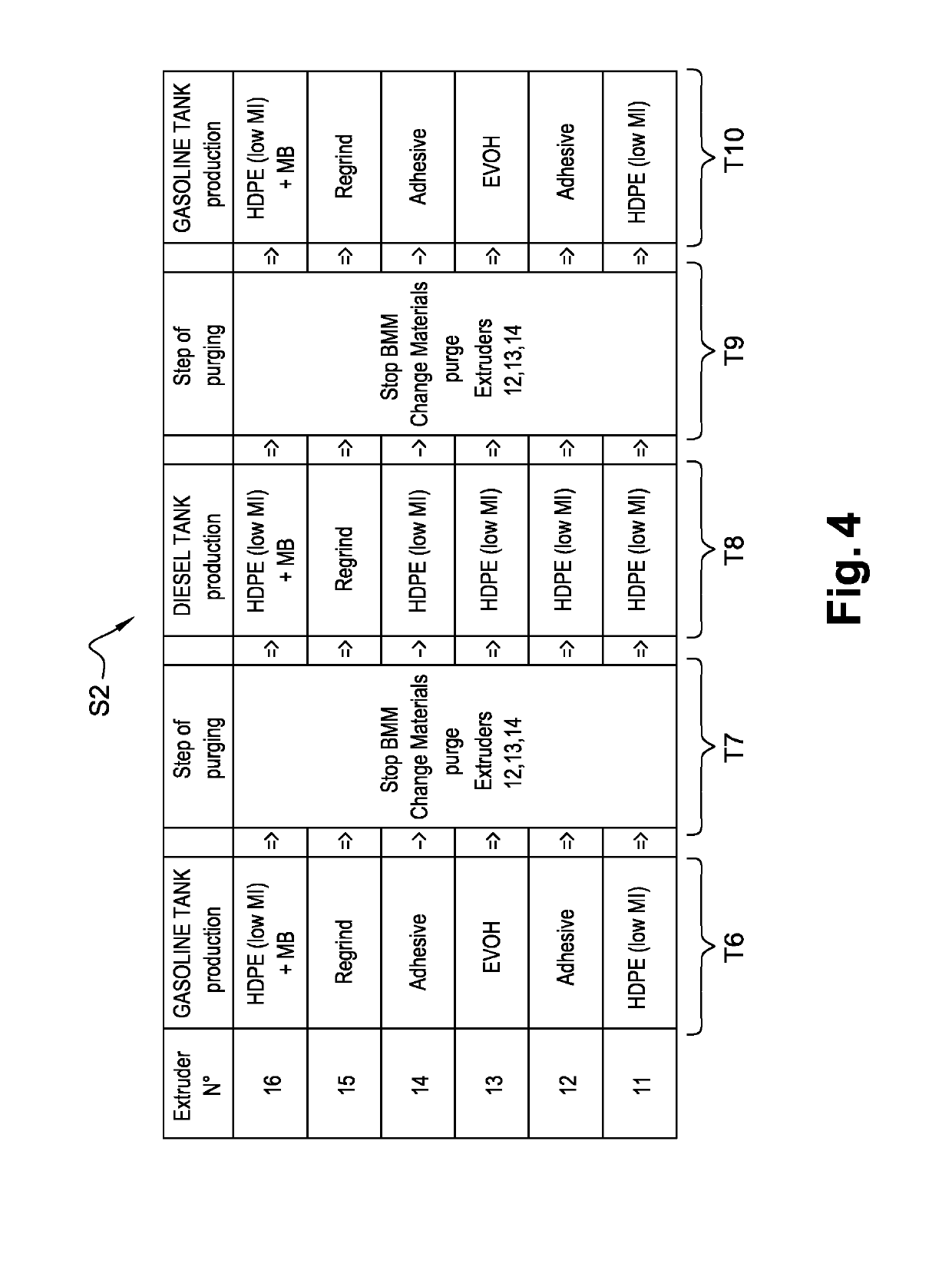
[0057]For clarity reason, the invention is described hereafter only for the particular case of the production of diesel tanks and gasoline tanks for motor vehicles. It is to note that the invention can be applied in the same manner to the case of the production of diesel filler pipes and gasoline filler pipes for motor vehicles.

[0058]The same reference numerals are used to indicate the same elements (or functionally-similar elements) throughout the separate FIGS. 1 to 4.

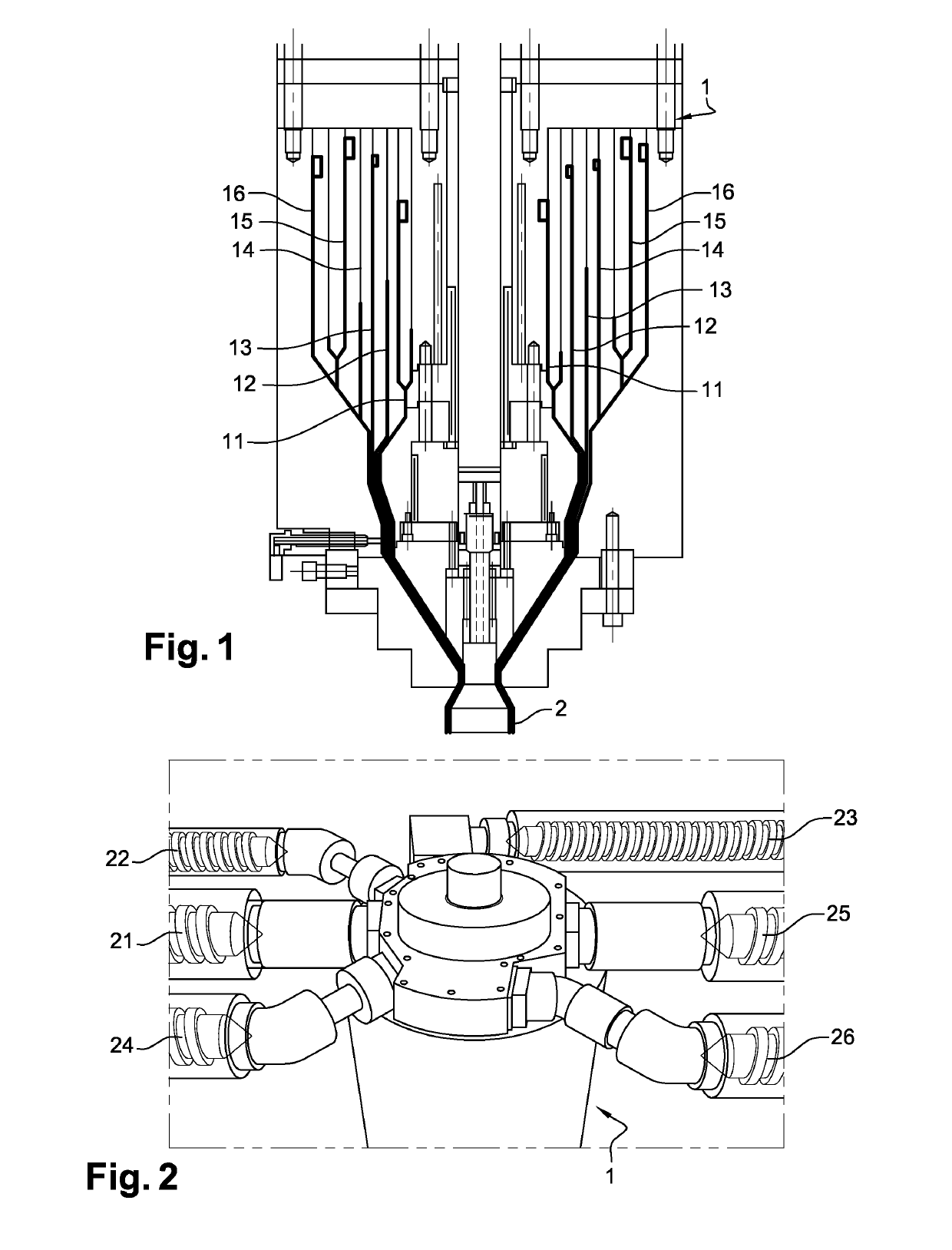
[0059]FIG. 1 is a cross sectional view of a coextrusion head 1 according to a particular embodiment of the present invention. The coextrusion head 1 is a part of an extrusion-blow moulding machine (not shown). The coextrusion head 1 is in charge of producing a multilayer parison 2.

[0060]In this particular embodiment, the coextrusion head 1 comprises six extruders 11, 12, 13, 14, 15 and 16. In another embodiment, the coextrusion head can comprise more than or less than six extruders. Each extruder is in charge of extr...


PUM

PropertyMeasurementUnit
timeaaaaaaaaaa
densityaaaaaaaaaa
adhesiveaaaaaaaaaa

Abstract

A process for manufacturing a diesel tank or filler pipe by an extrusion-blow molding machine configured to manufacture a gasoline tank or filler pipe. The extrusion-blow molding machine includes a coextrusion head including at least one extruder configured to provide during a first period of time a first material that is a barrier to liquids and / or gases, such that during the first period of time the coextrusion head produces a first multilayer parison from which the gasoline tank or filler pipe can be manufactured. The extruder is further configured to provide during a second period of time a second material distinct from the first material, such that during the second period of time the coextrusion head produces a second multilayer parison from which the diesel tank or filler pipe can be manufactured.

Description

FIELD OF THE INVENTION[0001]The present invention relates to a process for manufacturing hollow bodies, and particularly fuel tanks and filler pipes for motor vehicles. More precisely, it relates to the manufacture of a thermoplastic diesel tank or filler pipe.PRIOR ART[0002]For clarity reason, the problems of the prior art are described hereafter only for the particular case of the production of diesel tanks and gasoline tanks for motor vehicles. It is to note that similar problems are encountered in the case of the production of diesel filler pipes and gasoline filler pipes for motor vehicles.[0003]Thermoplastic fuel tanks are widely used in motor vehicles. Diesel vehicles are equipped with diesel tanks and gasoline (i.e. petrol) vehicles are equipped with gasoline tanks. A hybrid vehicle may be equipped either with a diesel tank or a gasoline tank.[0004]Generally, the wall of a diesel tank is composed of a single thermoplastic layer. It is known to manufacture a diesel tank by me...

Claims


Application Information

Patent Timeline
Patent Type & Authority Patents(United States)
IPC IPC(8): B29C49/04B29C48/25F16L9/12B29C49/22B29C49/00B60K15/04B60K15/03B29C48/21B29C48/27B29C48/22B29C48/09B29K23/00B29L23/00B29L31/00
CPCB29C49/04B29C48/2692B29C49/0005B29C49/22B60K15/03177B60K15/04F16L9/123B29C48/21B60K2015/03046B29C48/09B29C48/22B29C48/2715B29K2023/065B29K2023/086B29K2995/0067B29K2995/0069B29L2023/22B29L2031/7172
Inventor KOSAKO, SEIJIBOUCAUX, ERICSHIMOTAKE, KOICHIROCHEN, YONG
Owner PLASTIC OMNIUM ADVANCED INNOVATION & RES SA
Why Eureka
Try Eureka