Method for dripless liquid color delivery using a dripless liquid color feed throat adaptor

a drip-free, liquid color technology, applied in the direction of transportation and packaging, coatings, other domestic articles, etc., can solve the problems of liquid color drippage, difficult handling, and problems such as short length, and achieve the effect of eliminating the risk of dripping, short length, and easy cleaning

Inactive Publication Date: 2018-01-04
MAGUIRE STEPHEN B
View PDF0 Cites 0 Cited by
  • Summary
  • Abstract
  • Description
  • Claims
  • Application Information

AI Technical Summary

Benefits of technology

The patent text describes a design for a color delivery system in a machine. The system uses a small diameter Teflon tube that is fixed in place, eliminating the risk of dripping during color changes. The tube stays in the machine and is positioned to ensure that the inlet is higher than the outlet, so that any excess color is pushed out of the machine. Overall, this design allows for quick and safe color changes in the machine.

Problems solved by technology

Problems can arise if the liquid color contacts any portion of the feed throat as the liquid color is being fed to the screw.
Liquid color for coloring plastics is extremely viscous, somewhat like tar, and hence is very difficult to handle!
If the liquid color touches even the sides of the feed throat, this can present a problem due to the difficulty of clean up and the possibility of contamination of one color with another when color changeover is effectuated.
In the prior art, the most accepted way to introduce liquid color into the screw barrel and adjacent to the rotatable screw is to introduce the liquid color through a guide tube that passes through the feed throat and has its outlet end positioned close to the screw, so the liquid color does not exit the guide tube until it is well past the surfaces of the feed throat and other components, where spillage of the liquid color on to those surfaces could cause a problem.
A problem with current liquid color delivery systems as described immediately above is that when a color delivery tube is withdrawn, liquid color will drip from the open outlet end of the color delivery tube.
Any dripping of the liquid color creates a mess that is difficult to clean up due to the high viscosity, staining and other properties of liquid color.
Typically, the mess only gets worse and worse as time passes using current liquid color delivery techniques.

Method used


Image

  • Method for dripless liquid color delivery using a dripless liquid color feed throat adaptor
  • Method for dripless liquid color delivery using a dripless liquid color feed throat adaptor
  • Method for dripless liquid color delivery using a dripless liquid color feed throat adaptor

Examples


Embodiment Construction

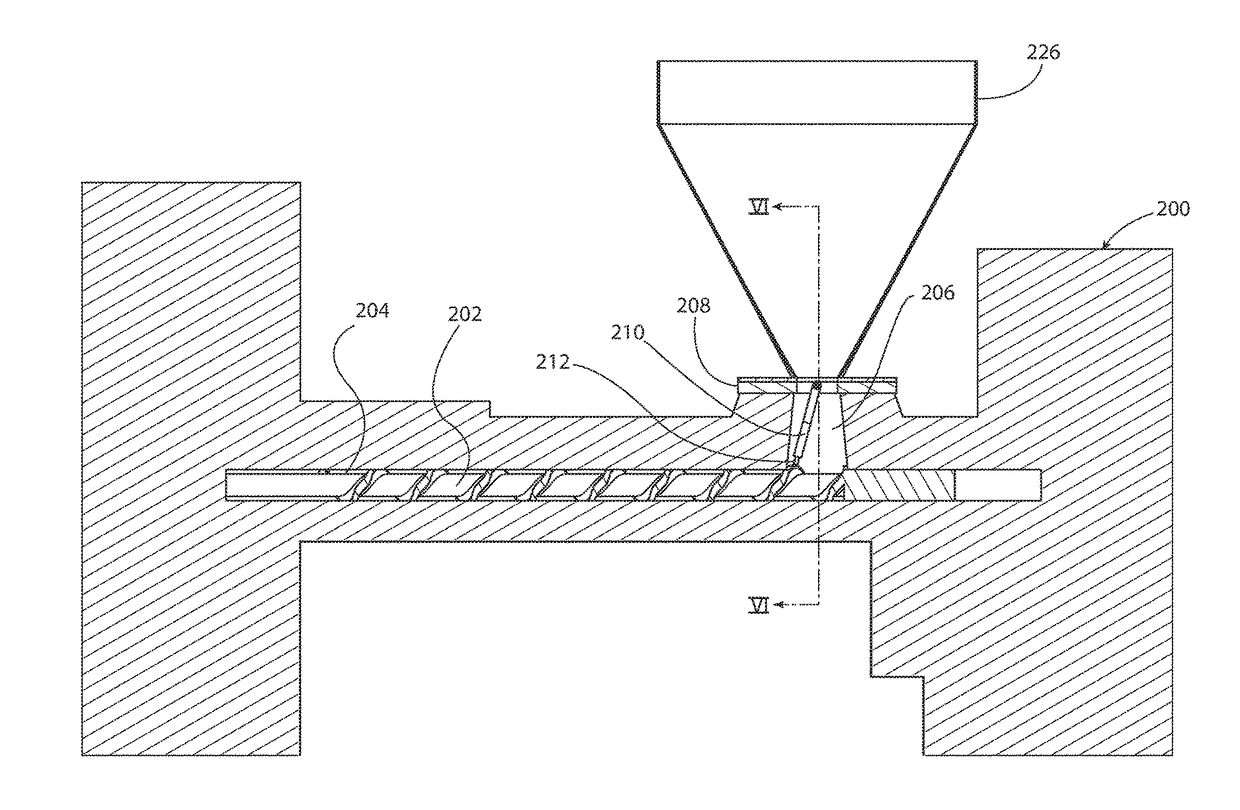
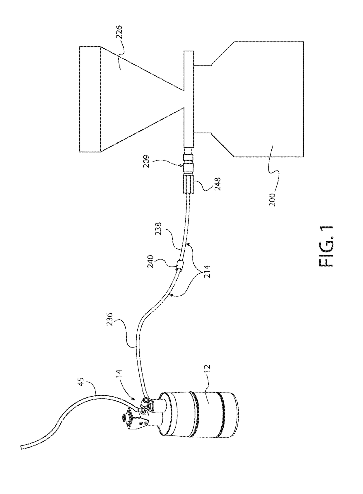
[0037]In this invention, soft aluminum tubing is used to fabricate a relatively rigid outer color delivery tube portion of a color feed conduit assembly. Soft aluminum tubing can be formed into a curve in the same manner that copper tubing can be formed; aluminum tubing is substantially lower in cost.

[0038]The invention further utilizes a compression fitting installed on the inlet end of the aluminum outer color delivery tube. The inlet end of the outer color delivery tube is exposed, outside the process machine. A compression adaptor fitting fits on to the aluminum outer color delivery tube. The compression fitting end is tightened, resulting in swaging the compression ferrule permanently onto the inlet end of the aluminum outer color delivery tube. The swaging locks the ferrule in place. A compression nut is also captured on the outer color delivery tube at the inlet end.

[0039]An adaptor fitting is provided for connection to the color delivery tube inlet end. The adaptor fitting c...


PUM

PropertyMeasurementUnit
lengthaaaaaaaaaa
diameteraaaaaaaaaa
areaaaaaaaaaaa

Abstract

Apparatus and methods for converting resin into colored finished or semi-finished plastic parts include a process machine having a barrel, a rotatable screw inside the barrel, and a color feed conduit assembly extending into the barrel for passage of liquid color through the color feed conduit assembly into proximity with the screw.

Description

CROSS REFERENCE TO RELATED PATENT APPLICATIONS[0001]This patent application is a 35 USC 120 division of co-pending U.S. patent application Ser. No. 14 / 105,958 filed 13 Dec. 2013 in the name of Stephen B. Maguire and entitled “Dripless Liquid Color Feed Throat Adaptor and Method for Dripless Liquid Color Delivery.”BACKGROUND OF THE INVENTIONField of the Invention[0002]This invention relates to molding and extrusion of plastic resin pellets to produce finished and semi-finished plastic products, and more particularly relates to using liquid color to color those finished and semi-finished plastic parts as the parts are being molded or extruded.Description of the Prior Art[0003]In the plastics industry, injection molding machines and extruders (herein collectively referred to as “process machines”) include a screw inside a barrel for melting the plastic resin pellets by working it by action of the screw against the resin as the screw rotates and driving the melted plastic forward throug...

Claims


Application Information

Patent Timeline
Patent Type & Authority Applications(United States)
IPC IPC(8): B29C47/10B29C45/18B29C47/08B29C48/29B29L31/00
CPCB29C47/0813B29C47/1063B29C47/1009B29C45/1816B29L2031/00Y10T137/0318Y10T137/85978B29K2995/002B29C48/2563B29K2105/0032B29C48/501B29B7/40B29B7/945B29B9/16B29B2009/163B29C48/29B29C48/286B29C48/2552
Inventor MAGUIRE, STEPHEN B.
Owner MAGUIRE STEPHEN B
Why Eureka
Try Eureka