Electrical receptacle connector and electrical plug connector

a technology of electrical receptacles and connectors, applied in the direction of coupling device connections, coupling protective earth/shielding arrangements, two-part coupling devices, etc., can solve problems such as how to solve a known structure problem, and achieve effective conducting and grounding, abutting resistance, and the effect of further reducing emi

Active Publication Date: 2016-10-04
ADVANCED CONNECTEK INC
View PDF12 Cites 15 Cited by
  • Summary
  • Abstract
  • Description
  • Claims
  • Application Information

AI Technical Summary

Benefits of technology

[0008]In conclusion, since the abutting pieces of the electrical plug connector is connected with the conductive piece of the electrical receptacle connector, effective conducting and grounding are achieved between the metal shell of the electrical plug connector and the metal shell of the electrical receptacle connector due to the connection of the abutting pieces and the conductive piece, and EMI can be further reduced. Furthermore, with the structural configuration of first cutout areas or second cutout areas of the abutting pieces, the abutting resistance for connecting the electrical plug connector with the electrical receptacle connector can be reduced, thereby allowing the electrical plug connector can be connected with the electrical receptacle connector with low insertion force and high withdrawal force.

Problems solved by technology

Therefore, how to solve the problem of a known structure is an issue that persons skilled in the relevant field should think.

Method used


Image

  • Electrical receptacle connector and electrical plug connector
  • Electrical receptacle connector and electrical plug connector
  • Electrical receptacle connector and electrical plug connector

Examples


Embodiment Construction

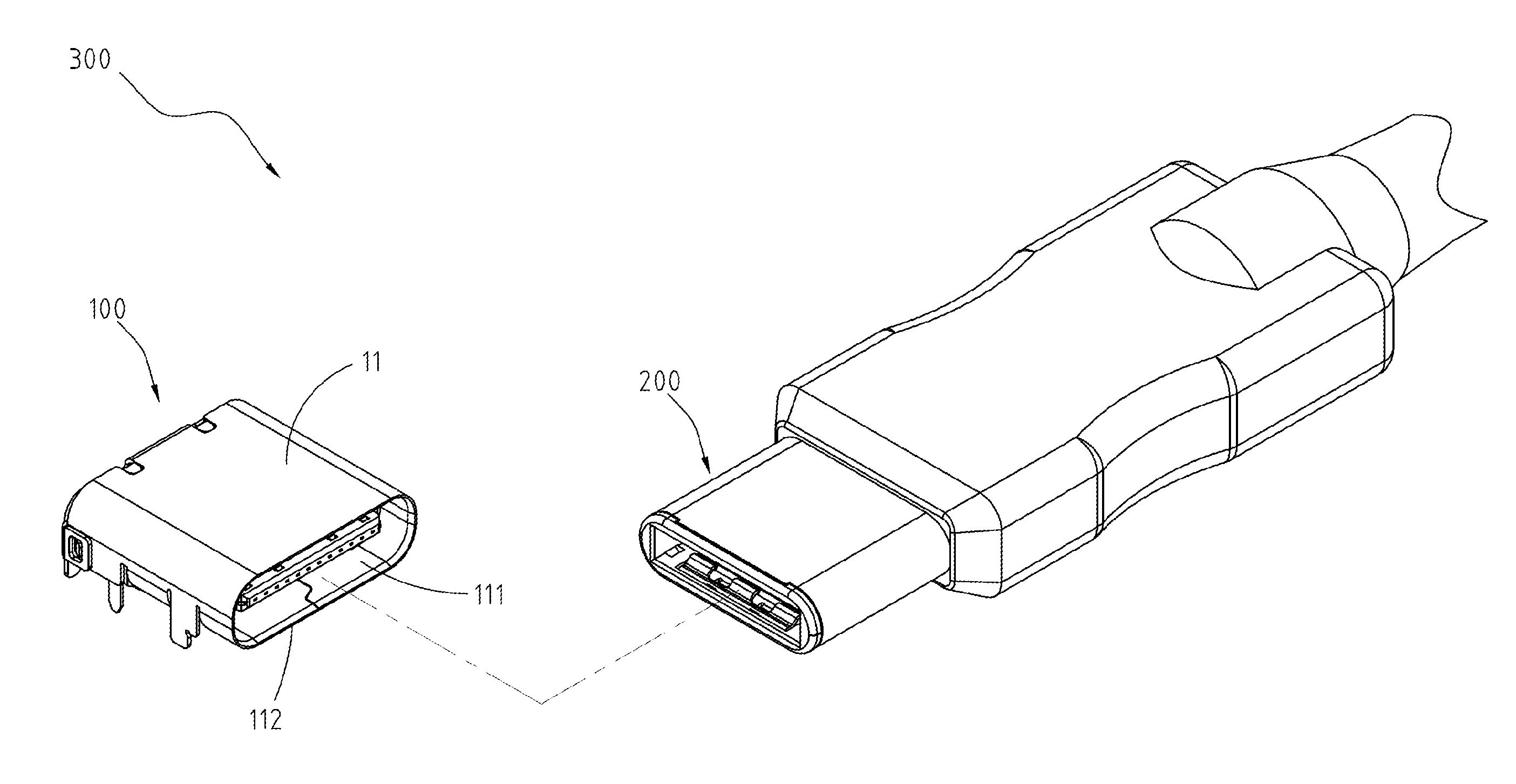
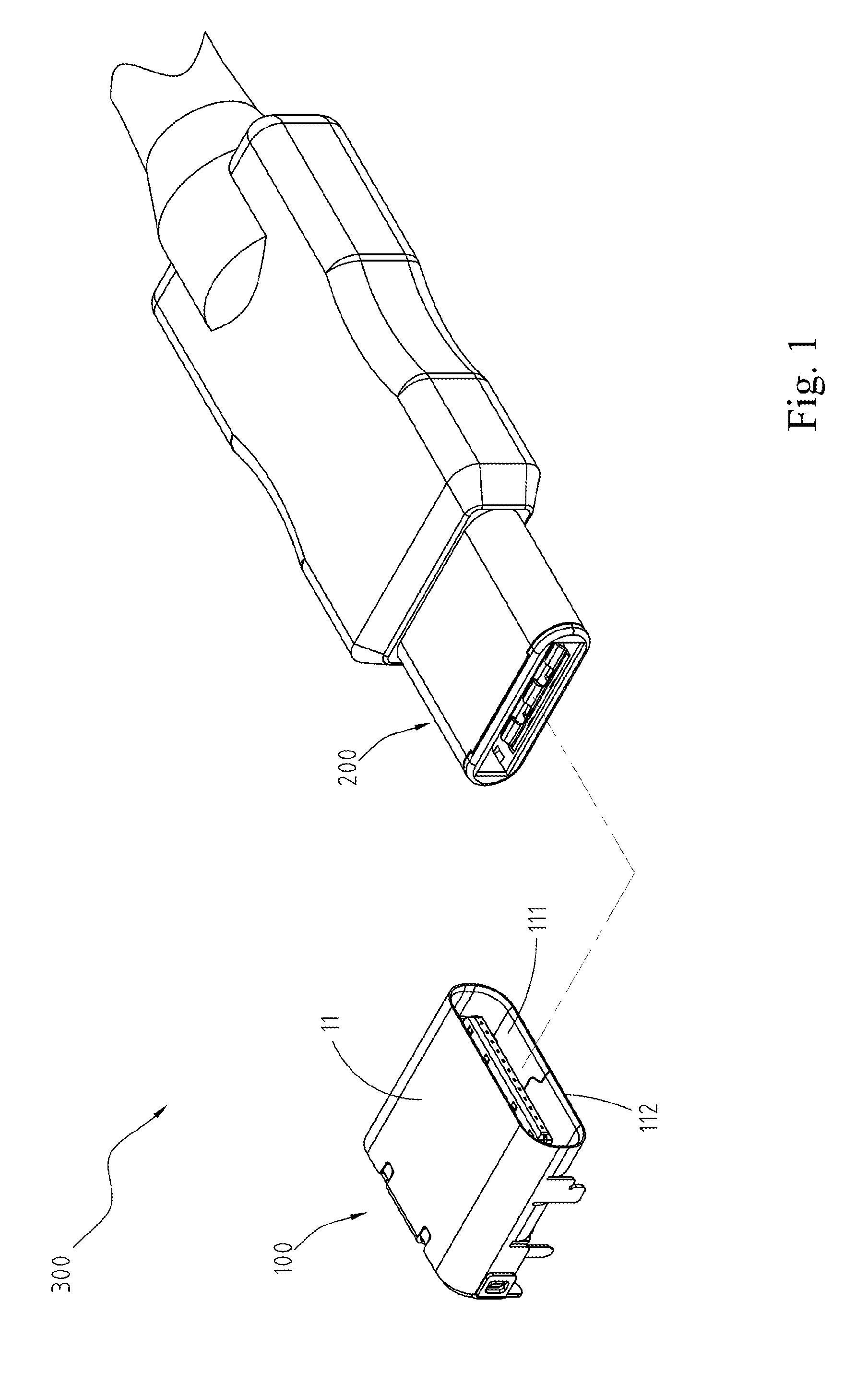
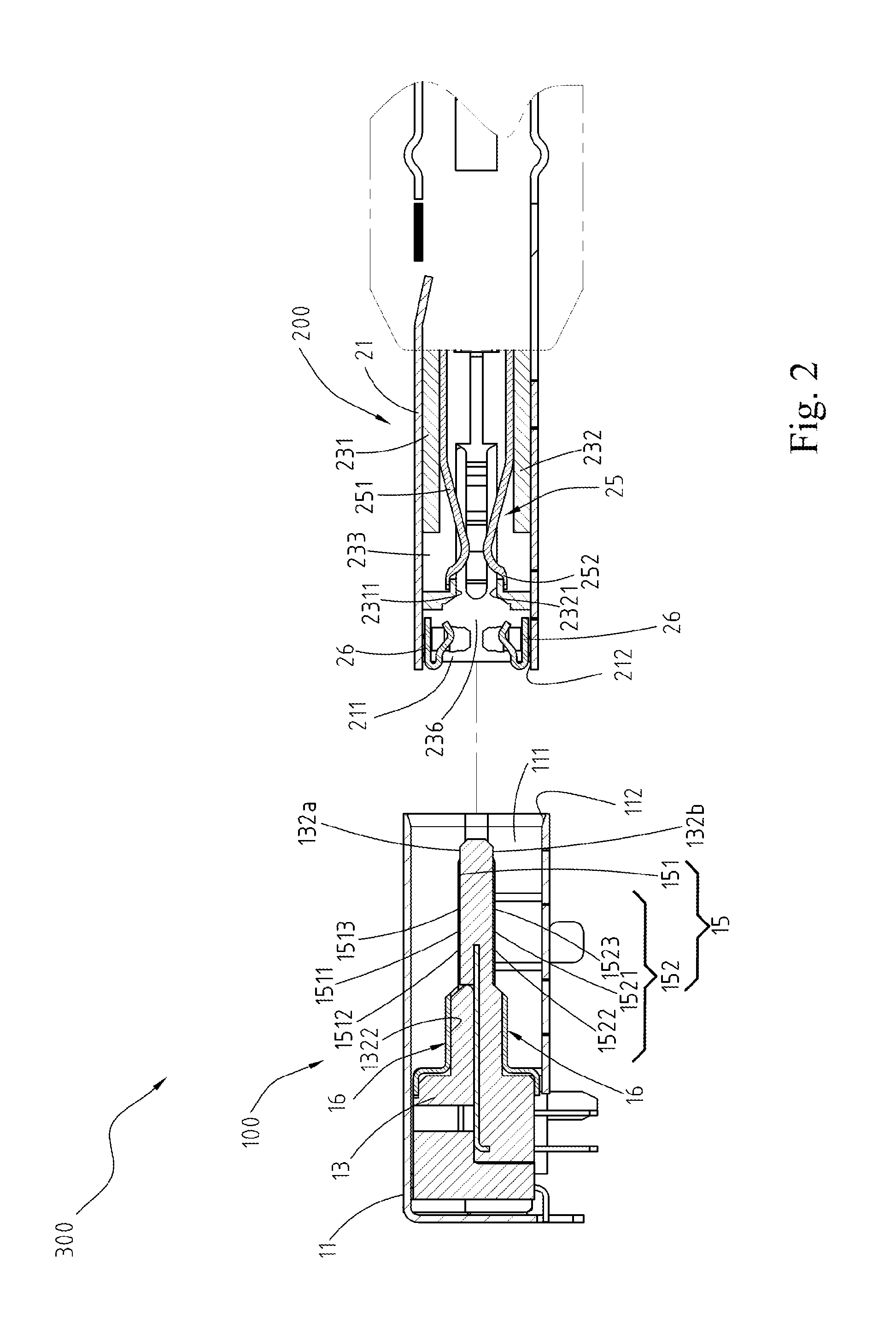
[0025]Referring to FIGS. 1, 2 and 3, the embodiment of an electrical connector assembly 300 according to the present invention is shown. FIG. 1 is an exploded view, FIG. 2 is an exploded side view, and FIG. 3 is a lateral view of the electrical connector assembly 300. The electrical connector assembly 300 according to the present invention mainly includes an electrical receptacle connector 100 and an electrical plug connector 200.

[0026]Referring to FIGS. 4 and 5, particularly, FIG. 4 clearly shows that a plurality of conductive pieces 16 is disposed at an insulation housing 13 while a metal shell 11 is eliminated from the electrical receptacle connector 100. The electrical receptacle connector 100 described herein is in accordance with the specification of a type-C USB connection interface and mainly includes a metal shell 11, an insulation housing 13, a plurality of receptacle terminals 15 and at least one conductive piece 16.

[0027]The metal shell 11 is a hollow shell, a receptacle...


PUM


Abstract

An electrical receptacle connector, provided to connect with an electrical plug connector, includes a metal shell, an insulation housing and a conductive piece. The conductive piece is disposed at a tongue portion of the insulation housing and includes a contact portion, two laterally soldering portions and an abutting portion. The contact portion is disposed at a rear contact region of the tongue portion, the two laterally soldering portions are respectively extending from two sides of the contact portion, and the abutting portion is extending from the contact portion to attach on a base portion of the insulation ho thus abutting against an inner wall of the metal shell.

Description

CROSS-REFERENCES TO RELATED APPLICATIONS[0001]This non-provisional application claims priority under 35 U.S.C. §119(a) on Patent Application No. 103214012 filed in Taiwan, R.O.C. on Apr. 21, 2014, the entire contents of which are hereby incorporated by reference.FIELD OF THE INVENTION[0002]The present invention relates to an electrical connector, and particularly to an electrical receptacle connector and an electrical plug connector for connected therewith.BACKGROUND[0003]Generally, an electrical connector interface adopts a Universal Serial Bus (USB) which is widely used by common consumers due to a plug-and-play characteristic of the USB, and nowadays a USB 2.0 transmission specification is developed to a USB 3.0 transmission specification with a faster transmission speed.[0004]Since the existing electronic product is designed to be downsized and when a USB electrical receptacle connector and other surrounding electronic elements on the electronic product are adjacent to each othe...

Claims


Application Information

Patent Timeline
Patent Type & Authority Patents(United States)
IPC IPC(8): H01R13/648H01R24/60H01R13/6583
CPCH01R24/60H01R13/6583H01R13/631H01R13/6581H01R24/00H01R24/20H01R2107/00
Inventor KAO, YA-FENTSAI, YU-LUNHOU, PIN-YUANWANG, WEN-YUTSAI, WEN-HSIENMACDOUGALL, ALAN ROBERT
Owner ADVANCED CONNECTEK INC
Why Eureka
Try Eureka