Frequency modulator apparatus of phase selection type, and frequency synthesizer of phase selection type

a frequency synthesizer and phase selection technology, applied in the direction of pulse technique, instruments, generating/distributing signals, etc., can solve the problems of reducing emi and emi in electronic equipment, and achieve the effect of reducing emi and easing the restriction on the phase range of modulated clock signals

Active Publication Date: 2006-02-02
THINE ELECTRONICS
View PDF6 Cites 16 Cited by
  • Summary
  • Abstract
  • Description
  • Claims
  • Application Information

AI Technical Summary

Benefits of technology

[0014] Accordingly, in view of the above-mentioned points, an object of the present invention is to provide a phase-selective type frequency modulator and a phase-selective type frequency synthesizer capable of easing the restriction on a phase range of a modulated clock signal.
[0017] According to the present invention, since the restriction on the phase range of the modulated clock signal can be eased, the EMI can be further reduced.

Problems solved by technology

With the rapid operation of electronic equipment, the EMI in the electronic equipment becomes a problem and the reduction of the EMI is required.
However, in the case where the above-mentioned clock signal generator is used, there is a problem as described below.

Method used


Image

  • Frequency modulator apparatus of phase selection type, and frequency synthesizer of phase selection type
  • Frequency modulator apparatus of phase selection type, and frequency synthesizer of phase selection type
  • Frequency modulator apparatus of phase selection type, and frequency synthesizer of phase selection type

Examples


Embodiment Construction

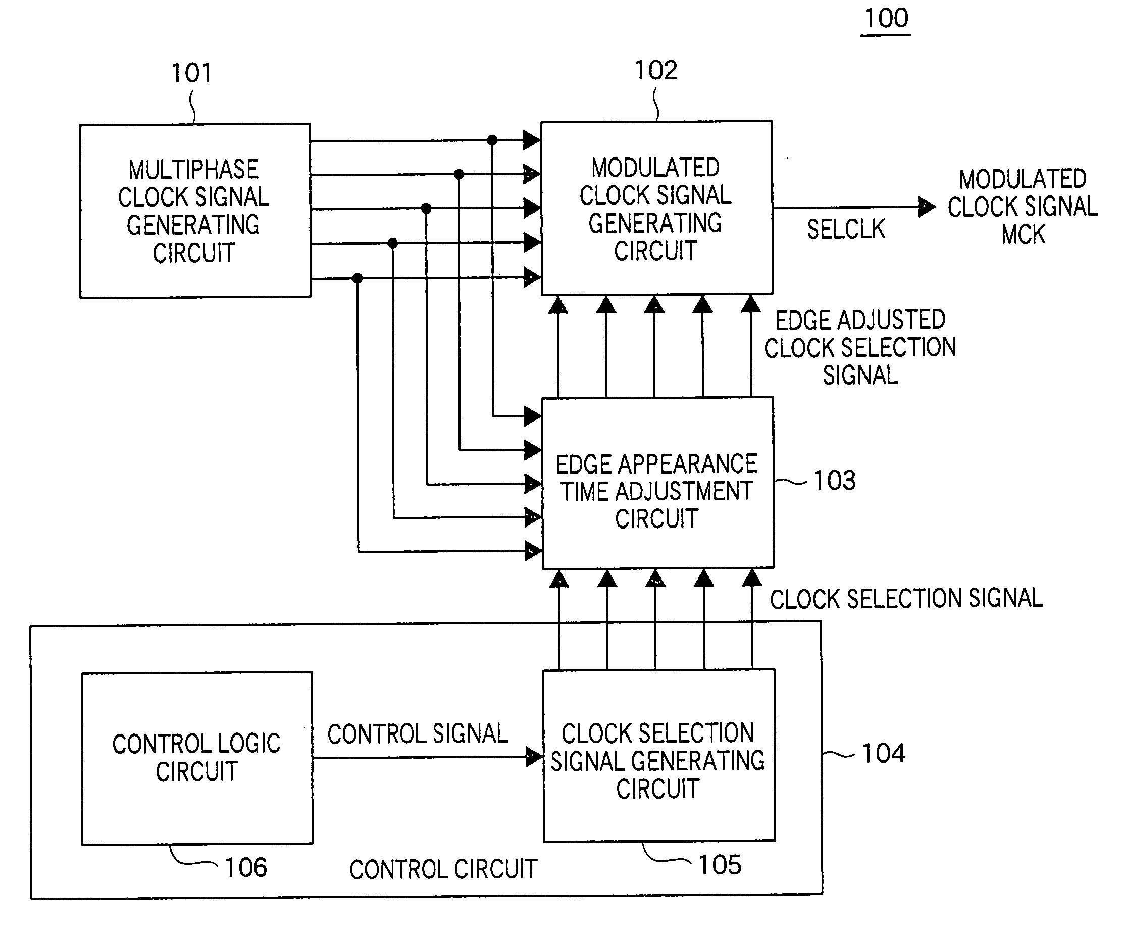
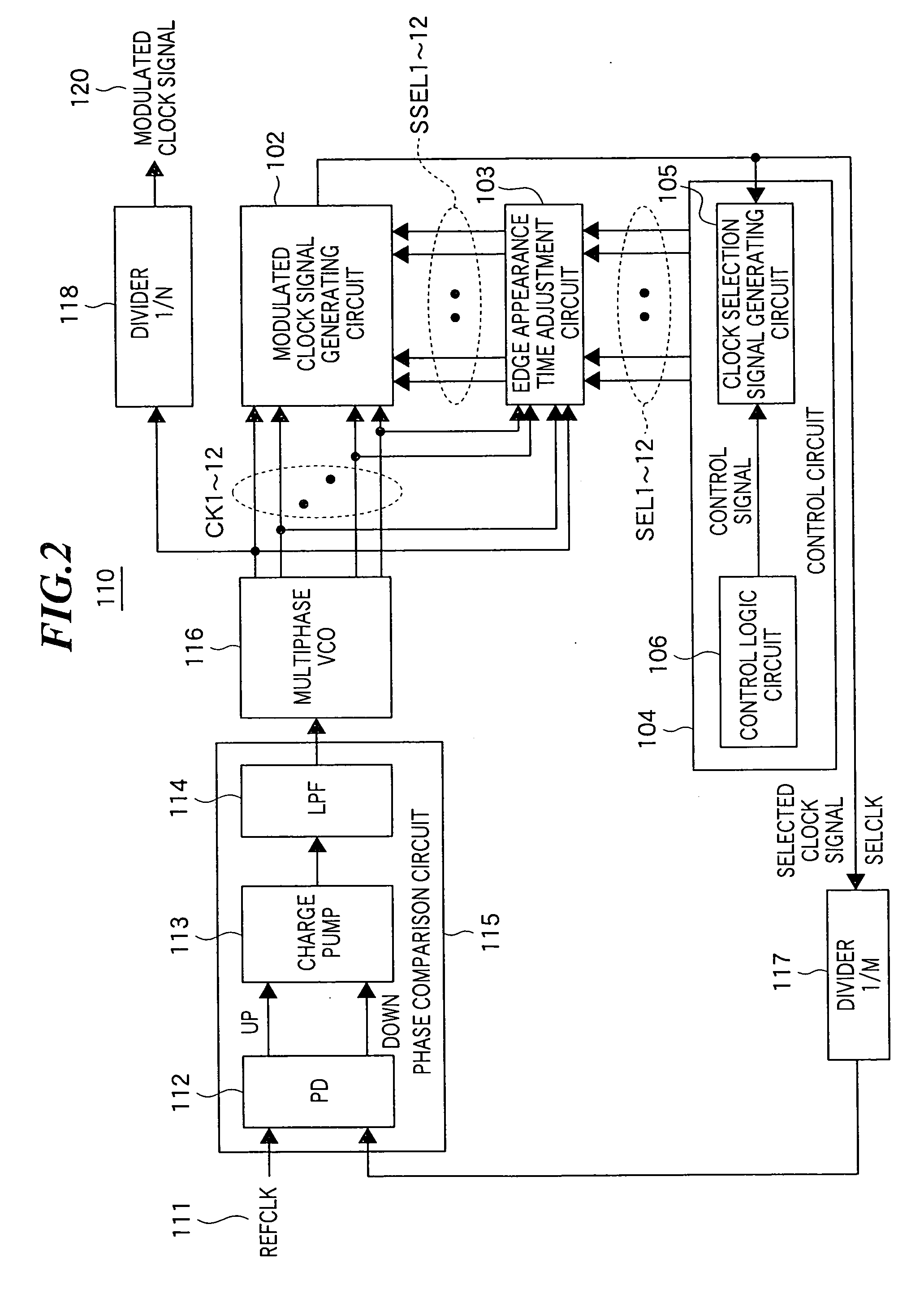
[0041] In a phase-selective type frequency modulator and a phase-selective type frequency synthesizer according to the present invention, in order to generate a modulated clock signal in which the restriction of phase valuable range is eased to reduce the EMI, a circuit is formed such that a rising edge appearance time and / or a trailing edge appearance time of one clock signal selected from N-phase clock signals and a rising edge appearance time and / or a trailing edge appearance time of a clock selection signal for selecting the clock signal may have time lag and may not overlap one another.

[0042] Here, in the case where a number “N” of phases of the N-phase clock signals is an integer number equal to or more than four, the phase-selective type frequency modulator and the phase-selective type frequency synthesizer according to the present invention exert effects.

[0043] More specifically, when a modulated clock signal is generated by selecting one clock signal (referred to as a “fi...


PUM


Abstract

A phase-selective type frequency modulator capable of easing the restriction on a phase range of a modulated clock signal. The phase-selective type frequency modulator includes a multiphase clock signal generating circuit 101 for generating N-phase clock signals; a control circuit 104 for sequentially activating one of first group of clock selection signals indicating a clock signal to be selected from the N-phase clock signals; an edge appearance time adjustment circuit 103 for adjusting a rising edge appearance time and / or a trailing edge appearance time of the first group of clock selection signals outputted from the control circuit 104 to output second group of clock selection signals; and a modulated clock signal generating circuit 102 for selecting one clock signal from the N-phase clock signals in accordance with an activated state of the second group of clock selection signals outputted from the edge appearance time adjustment circuit 103 to output a modulated clock signal MCK.

Description

TECHNICAL FIELD [0001] The present invention relates to a phase-selective type frequency modulator and a phase-selective type frequency synthesizer capable of reducing electromagnetic interference (hereinafter, referred to as “EMI”) in electronic equipment which transmits image data, etc. BACKGROUND ART [0002] With the rapid operation of electronic equipment, the EMI in the electronic equipment becomes a problem and the reduction of the EMI is required. As one technology for reducing the EMI in electronic equipment, a method employing a spread spectrum clock signal has been proposed. More specifically, jitter is intentionally generated so that a peak of a spectrum may not be generated at a particular frequency, or a frequency is varied gradually with a cycle, that provides no influence on the operation of the circuit, for example, a cycle in a range from several of kilo Hertz to several hundreds of kilo Hertz. [0003]FIG. 17 is a functional block diagram showing a configuration of a ...

Claims


Application Information

Patent Timeline
Patent Type & Authority Applications(United States)
IPC IPC(8): H04B1/16H04B1/06H04B7/00G06F1/04G06F1/08G09G3/20H03K3/03H03K5/15H03L7/08H03L7/099H03L7/18H04L7/00H04L7/033H04N5/04
CPCG06F1/08H03L7/18H03L7/0996H03K3/0322G06F1/04G09G3/20H03K5/15H03L7/08
Inventor OZAWA, SEIICHIOKAMURA, JUNICHI
Owner THINE ELECTRONICS
Why Eureka
Try Eureka