Novel highly-efficient high-power annular laser amplifier

一种激光放大器、高功率的技术,应用在激光器、激光器零部件、声子激发器等方向,能够解决维护成本高、全系统结构复杂、冗长等问题,达到放大器结构紧凑、提高提取效率、抑制衍射效应的效果

Active Publication Date: 2017-03-08
SUZHOU UNIV
View PDF4 Cites 18 Cited by
  • Summary
  • Abstract
  • Description
  • Claims
  • Application Information

AI Technical Summary

Problems solved by technology

First, in order to fully extract the energy in the medium, there are clear requirements for the energy of the amplified injection pulse at all levels; second, in order to isolate ASE, the off-axis design is usually considered in multi-pass amplifying devices, which reduces the filling factor; third, the current In some devices, variable caliber, single-pulse unidirectional transmission amplification is usually used, and the energy storage and extraction efficiency of the amplifier is low; fourth, the whole system structure is complex and lengthy, expensive, and maintenance costs are high

Method used


Image

  • Novel highly-efficient high-power annular laser amplifier
  • Novel highly-efficient high-power annular laser amplifier

Examples


Embodiment 1

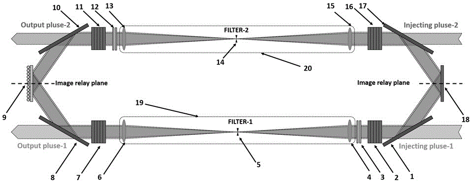
[0043] Such as figure 1 As shown, Embodiment 1 of the present invention provides an amplification scheme of a double-pulse injection ring laser amplifier, which can obtain the highest energy storage and extraction efficiency of the amplifying medium under the condition of maximum output energy. The novel high-efficiency and high-power ring laser amplifier includes 4 polarizing reflectors, 4 laser gain media, 4 lenses, 2 filter apertures, 2 electro-optic switches, 1 wavefront corrector and 1 reflector.

[0044] The first injection pulse and the second injection pulse are simultaneously injected into the ring laser amplifier by the first polarizing mirror 1 and the fourth polarizing mirror 17 respectively.

[0045] The first injection pulse is injected by the first polarizing mirror 1, and the first polarizing mirror 1 is used to transmit vertical (or horizontal) linearly polarized light and reflect horizontal (or vertical) linearly polarized light. The vertically (or horizonta...

Embodiment 2

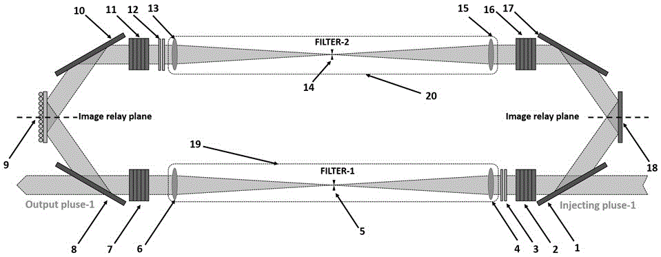
[0048] Such as figure 2 As shown, Embodiment 2 of the present invention provides a ring laser amplifier with single pulse injection, which can obtain maximum energy output. The ring laser amplifier includes 4 polarizing reflectors, 4 laser gain media, 4 lenses, 2 filter apertures, 2 electro-optical switches, 1 wavefront corrector and a reflector.

[0049] The first injection pulse is injected by the first polarizing mirror 1, and the first polarizing mirror 1 is used to transmit vertical (or horizontal) linearly polarized light and reflect horizontal (or vertical) linearly polarized light. The vertically (or horizontally) linearly polarized light enters the first laser gain medium 2 through the first polarizing mirror 1, and the laser light is amplified. The amplified vertically (or horizontally) linearly polarized light is incident on the first electro-optic switch 3, and the electro-optic switch works to change its polarization state. Horizontally (or vertically) linearly...


PUM


Abstract

The invention discloses a novel highly-efficient high-power annular laser amplifier. The amplifier comprise four polarization reflection mirrors, four laser gain media, four lenses, two filtering hole stops, two electro-optical switches, one wavefront corrector and one reflection mirror. According to the invention, the amplifier is suitable for double-pulse direction transmission amplification and coaxial annular amplification of any transmission type gain medium, so energy storage and extraction efficiency of the laser gain medium is effectively increased and high-power laser output is acquired. Through the annular amplifier, annular amplification for any time can be achieved theoretically, quality of output light beams is effectively controlled and limitation on injected energy is loosened. Two space filters are adopted, so space modulation in the light beams can be effectively filtered. The image faces of the space filters are connected with object faces end to end, so diffraction effects of transmission in the cavity of the laser pulse can be restrained, and amplification with the high light beam quality is kept. The amplifier is of an annular structure, so the system structure is more compact.

Description

technical field [0001] The invention relates to a laser amplifier, in particular to a novel high-efficiency and high-power ring laser amplifier. Background technique [0002] Following the MOPA (Master Oscillator Power Amplifier) ​​technology, the new generation of laser technology represented by multi-pass amplification has greatly promoted the development of high-power laser devices, but there are still many problems. First, in order to fully extract the energy in the medium, there are clear requirements for the energy of the amplified injection pulse at all levels; second, in order to isolate ASE, the off-axis design is usually considered in multi-pass amplifying devices, which reduces the filling factor; third, the current In some devices, variable aperture, single pulse and one-way transmission amplification are usually used, and the energy storage and extraction efficiency of the amplifier is low; fourth, the whole system structure is complicated and lengthy, expensive...

Claims


Application Information

Patent Timeline
Patent Type & Authority Applications(China)
IPC IPC(8): H01S3/083H01S3/10
CPCH01S3/083H01S3/1024H01S3/07H01S3/235Y02A90/10
Inventor 袁孝张翔张小民虞天成高帆
Owner SUZHOU UNIV
Why Eureka
Try Eureka