Time sliced architecture for graphics display system

a graphics display system and time-sliced technology, applied in the direction of architecture with multiple processing units, static indicating devices, instruments, etc., can solve the problems of high cost of blending the various planes, large cost of rendering data paths, and high cost of electrical circuitry required to fabricate these components. , to achieve the effect of reducing the number of data paths, high quality and high area efficiency design of graphics display systems

Inactive Publication Date: 2005-12-08
SONY CORP +1
View PDF14 Cites 18 Cited by
  • Summary
  • Abstract
  • Description
  • Claims
  • Application Information

AI Technical Summary

Benefits of technology

[0015] The data processing apparatus of the present invention provides optimization and resource sharing strategies for a graphics display system. One aspect of the invention is the reuse of the rendering data path for all windows of a plane to reduce the number of data paths. Another aspect of the invention is a modular and scalable time sliced approach to achieve a highly area efficient design of a graphics display system while providing a high quality user interface for multiple application planes with multiple applications windows on a normal silicon chip with low power requirements. The present invention therefore provides a system and method of reducing the number of component circuitry that may be required to design a multimedia graphics chip to support multiple applications that require multiple window engines for generating multiple applications windows.

Problems solved by technology

In a conventional graphics system for displaying multiple types of graphics and pixel data, the electrical circuitry required to fabricate these components is expensive, bulky and consumes substantial power.
Additionally, there would be the cost of blending the various planes together.
The cost of rendering data paths is usually large due to the number of lookup tables, multipliers, adders, and so forth.
The additional components must each be placed on the limited surface area of the graphics chip and contribute to heat generation while adding to the delay of data processed by the graphics chip.

Method used


Image

  • Time sliced architecture for graphics display system
  • Time sliced architecture for graphics display system
  • Time sliced architecture for graphics display system

Examples


Embodiment Construction

[0036] Referring more specifically to the drawings, for illustrative purposes the present invention is embodied in the apparatus generally shown in FIG. 3 through FIG. 9. It will be appreciated that the apparatus may vary as to configuration and as to details of the parts, and that the method may vary as to the specific steps and sequence, without departing from the basic concepts as disclosed herein.

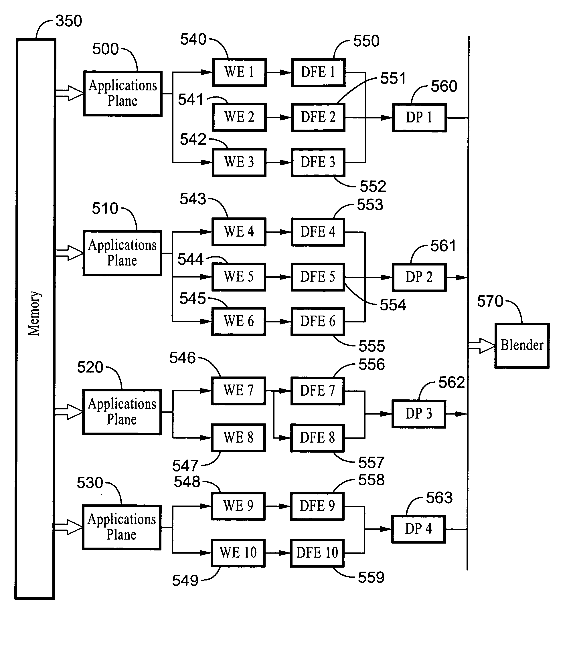
[0037] The present invention provides for the reduction in the number of elements in graphics system chip component circuitry as a consequence of sharing the rendering data paths for pixel processing in a graphics display engine to the same display plane. Additional aspects of the invention provide further improvement to the sharing, by utilizing time slicing, switching fabric architecture, and other enhancements.

[0038]FIG. 3 illustrates by way of an example embodiment of a graphics display system 300 which is preferably contained on an integrated circuit 310 for receiving graphics si...


PUM


Abstract

A system and method for rendering multiple windows across multiple display planes utilizing a sliced rendering data pathway architecture for achieving a highly area efficient design of the graphics display system. Windows across multiple display planes are rendered from direct memory access fetch engines retrieving pixel data from memory. Rendering data pathways are shared between direct memory access fetch engines directed to a single display plane. Furthermore, the rendering data pathways can be time sliced wherein data from multiple planes are time multiplexed through the rendering pathway. The invention allows creating a graphical engine with a lower gate count than conventional circuits. The resultant system is modular and scalable, while being customizable from lower power applications to HDTV sets.

Description

CROSS-REFERENCE TO RELATED APPLICATIONS [0001] Not Applicable STATEMENT REGARDING FEDERALLY SPONSORED RESEARCH OR DEVELOPMENT [0002] Not Applicable INCORPORATION-BY-REFERENCE OF MATERIAL SUBMITTED ON A COMPACT DISC [0003] Not Applicable NOTICE OF MATERIAL SUBJECT TO COPYRIGHT PROTECTION [0004] A portion of the material in this patent document is subject to copyright protection under the copyright laws of the United States and of other countries. The owner of the copyright rights has no objection to the facsimile reproduction by anyone of the patent document or the patent disclosure, as it appears in the United States Patent and Trademark Office publicly available file or records, but otherwise reserves all copyright rights whatsoever. The copyright owner does not hereby waive any of its rights to have this patent document maintained in secrecy, including without limitation its rights pursuant to 37 C.F.R. § 1.14. BACKGROUND OF THE INVENTION [0005] 1. Field of the Invention [0006] Th...

Claims


Application Information

Patent Timeline
Patent Type & Authority Applications(United States)
IPC IPC(8): G06F15/16G06F15/167G06F15/80G06T1/20
CPCG09G5/14G09G2360/128G09G2340/125G09G5/397
Inventor MUNDAY, TARJINDER SINGHGADRE, SHIRISHKAO, JEAN SWEYPALUCH, EDWARD J.
Owner SONY CORP
Why Eureka
Try Eureka