Binding member removing apparatus, automatic document feeder, sheet processing apparatus, and image forming apparatus

a technology of automatic document feeder and removing apparatus, which is applied in the direction of electrographic process apparatus, thin material processing, instruments, etc., can solve the problems of inability to cut and remove parts of bundles of paper, conventional binding member removing apparatus mentioned above, and inevitably destined to suffer the restriction of freedom of disposition of removing units, etc., to achieve the effect of easing the restriction of freedom of disposition

Inactive Publication Date: 2005-05-03
MINOLTA CO LTD
View PDF11 Cites 16 Cited by
  • Summary
  • Abstract
  • Description
  • Claims
  • Application Information

AI Technical Summary

Benefits of technology

[0021]An object of this invention is to provide a binding member removing apparatus which is endowed with a staple recovering facility capable of easing the restriction on the freedom of disposition of the means for removing the binding member from the bundle of sheets of paper and particularly ensuring the recovery of the staple even when the removing means is so disposed as to enable the binding member to be removed from the upper side of the bundle of sheets of paper, and an automatic document feeder, a sheet processing apparatus, and an image forming apparatus which are provided with this binding member removing apparatus.
[0023]Since this aspect of the invention enables the binding member removed from the bundle of sheets of paper to be forcibly moved by the moving unit, it heightens the freedom of disposition of the removing unit or the moving unit and, even when the binding member is extracted and removed from the upper side of the bundle, for example, enables the moving unit to attain infallible removal of the binding member from the neighborhood of the bundle of sheets of paper.
[0024]Another object of this invention is to provide a binding member removing apparatus which is capable of easily and infallibly removing the binding member from the bundle of sheets of paper by the use of one inserting member without inflicting damage on the bundle of sheets of paper, and an automatic document feeder, a sheet processing apparatus, and an image forming apparatus which are provided with the binding member removing apparatus.
[0026]This aspect of the invention enables one inserting member to effect removal of a binding member of a varying size by causing a fixed number of elongated parts to be passed between the bundle of sheets of paper and the binding member and held fast therein. This removal of the binding member Scan be attained infallibly and easily even when the position of the inserting member relative to the binding member is deviated more or less.
[0029]Still another object of this invention is to provide a binding member removing apparatus which is capable of extracting the binding member with relatively small force and, at the same time, preventing the sheets of paper from sustaining breakage while the binding member of the shape of a needle provided with opposite pointed ends is extracted therethrough, and an automatic document feeder, a sheet processing apparatus, and an image forming apparatus which are provided with the binding member removing apparatus.
[0030]One aspect of this invention consists in a binding member removing apparatus for removing a binding member from a bundle of sheets of paper which comprises an inserting member to be passed between said bundle of sheets of paper and said binding member binding said bundle of sheets of paper, said inserting member comprising a first inserting member to be passed between a first face of said bundle of sheets of paper and said binding material and a second inserting member to be passed between a second face of said bundle of sheets of paper and said binding member, and an automatic document feeder, a sheet processing apparatus, and an image forming apparatus which are provided with the binding member removing apparatus. This aspect of the invention, therefore, enables the binding member to be extracted with relatively small force.

Problems solved by technology

It, therefore, is incapable of cutting and removing part of the bundle of sheets of paper.
The conventional binding member removing apparatus mentioned above, however, have various problems as follows.
For the purpose of securing the path of recovery of this description, therefore, the removing unit is inevitably destined to suffer the freedom of disposition thereof to be restricted.
Particularly, the ADF which is provided with the binding member removing apparatus is not capable of adopting a structure allowing the staple to be removed upward from a bundle of sheets of paper mounted on the ADF because the removing unit is required to assume its position beneath the staple and cause the staple to be extracted from the lower side of the bundle by all means.
This requirement poses a problem to the ADF of the type which particularly requires the document sheets to be mounted with the image face thereof held upward.
If the ADF is provided with the removing unit which is adapted to extract the staple from the lower side of the bundle, the effect of automating the ADF will be inevitably impaired because the bundle of document sheets requiring removal of the staple must be mounted temporarily as held downward, i.e. in the direction opposite the direction in which the bundle is mounted for the purpose of conveyance by the ADF and, after the subsequent extraction of the staple, the bundle must be reversed so as to turn the image faces of the document sheets upward.
As a result, the problems of readapting the construction of the ADF itself and altering the construction of the copying machine etc. ensue.
Secondly, the extraction type binding member removing apparatus must be provided with an inserting member which fits the staple.
If the inserting member which does not fit the staple is forcibly used, the problem of not only rendering removal of a staple difficult but also possibly damaging the bundle of sheets of paper ensue.
This problem occurs not merely on the apparatus which effects removal of the binding member automatically but likewise on the manual binding member removing apparatus which effects removal of the binding member manually.
As a result, it suffers an increase in cost.
Further, this problem occurs on the ADF which is provided with the binding member removing apparatus.
To be specific, the apparatus which effects removal of the binding member automatically suffers an increase not only in cost but also in size of the apparatus itself because it requires a plurality of inserting members to be accommodated in the interior of the apparatus.
The binding member removing apparatus of the type which pulls a staple out of a bundle of sheets of paper by passing one inserting member between the bundle of sheets of paper and the staple and jerking the inserting member in the direction of expelling the staple has the problem of tending to inflict damage on the bundle of sheets of paper unless the inserting member is passed infallibly between the bundle of sheets of paper and the staple binding this bundle and then moved smoothly.
Thirdly, the conventional apparatus mentioned above have no consideration for the question as to what measure is to be taken when the apparatus fails to remove the binding member.
As a result, the sheets of paper in the process of conveyance bring such problems as blocking the path of conveyance, sustaining breakage, and inflicting damage to the ADF.
If the staple which has escaped removal is left advancing onto the platen glass of the copying machine or the scanner, it will have the possibility of inflicting damage to the surface of the platen glass.
Further, the extraction type binding member removing apparatus has the possibility that when the staple having the opposite leading end parts thereof driven through the bundle of sheets of paper and then folded toward each other is extracted from one face side of the bundle of sheets of paper, the folded opposite leading end parts will inflict damage to the individual sheets of paper forming the bundle.

Method used


Image

  • Binding member removing apparatus, automatic document feeder, sheet processing apparatus, and image forming apparatus
  • Binding member removing apparatus, automatic document feeder, sheet processing apparatus, and image forming apparatus
  • Binding member removing apparatus, automatic document feeder, sheet processing apparatus, and image forming apparatus

Examples


first example

[0055]The first example is a copying machine which is provided with an automatic document feeder incorporating therein the binding member removing apparatus according to this invention.

>

[0056]First, the general construction of the copying machine and the operation thereof will be described.

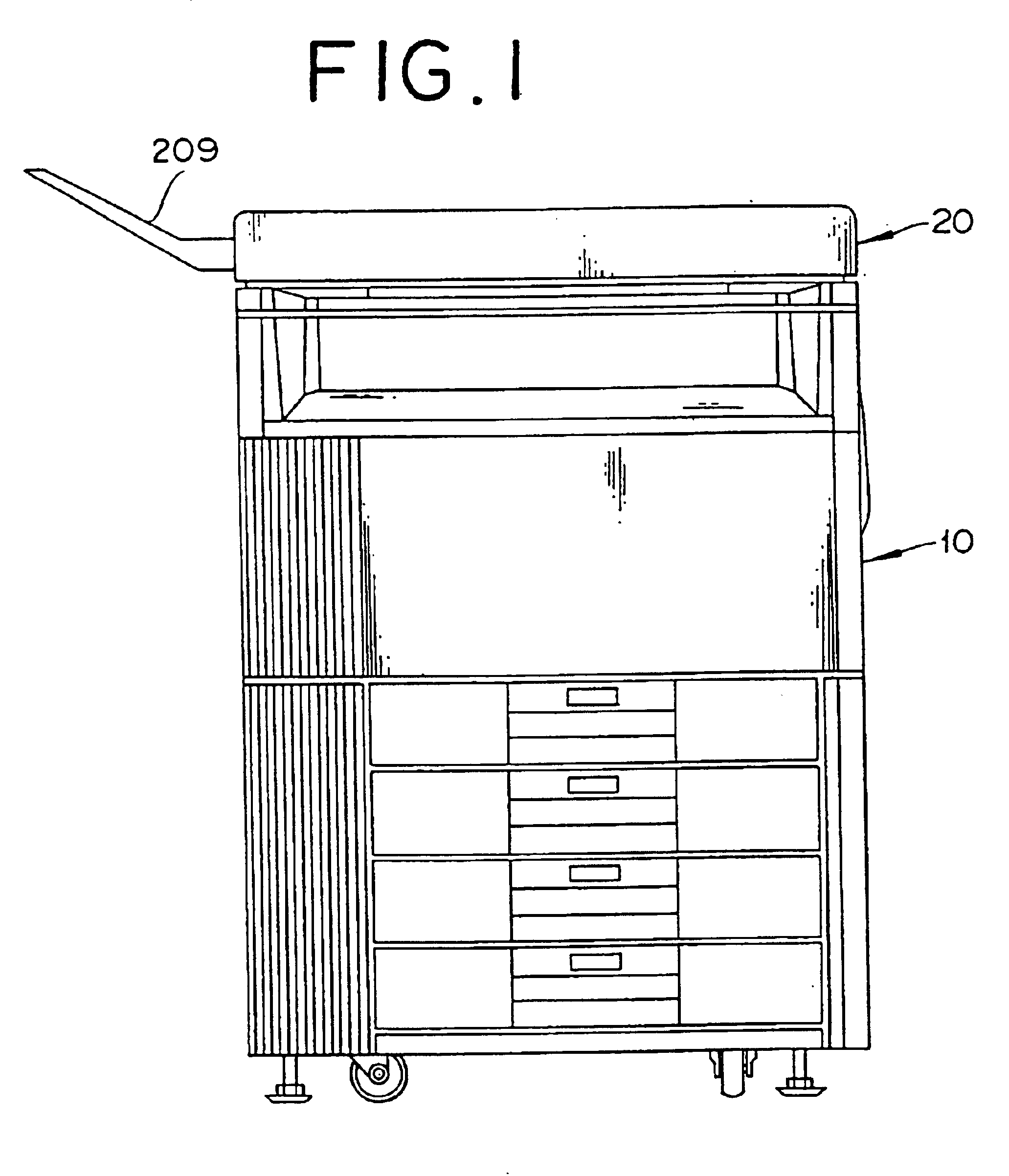
[0057]FIG. 1 is a side view of the copying machine provided with the automatic document feeder.

[0058]The copying machine illustrated in FIG. 1 is provided on a main body of the copying machine with an automatic document feeder (ADF) 20. The ADF 20 picks document sheets one by one from a bundle of document sheets mounted thereon and conveys them onto a platen glass in the upper part of the copying machine proper 10. The copying machine proper 10 is the so-called digital copying machine operating by a procedure which comprises causing an image reader (not shown) in the copying machine proper to read the document sheets conveyed by the ADF 20, storing the read image temporarily in a memory, optionall...

example 1

OF MODIFICATION OF THE RECOVERING DEVICE

[0091]Now, example 1 of modification of the recovering device will be described below. In the following examples of modification of the recovering device, the moving units provided therefor are varied in form. In the following description, members possessing a like function will be denoted by a like reference numeral and will be omitted from the description.

[0092]This recovering device 500a, as illustrated in FIG. 11, is identical in basic structure with the recovering device mentioned above. Specifically, a moving belt 522 is suspended in an endless state as passed around the supporting roller 503 and the driving roller 504 which are provided in the case 501 and the receiving box 505 and the blade 506 are disposed in the proximity of the end part on the right side in the bearings of the diagram.

[0093]The recovering device 500a differs from the recovering device mentioned above in respect that the moving belt itself is not a magnetic body and ...

example 2

OF MODIFICATION OF THE RECOVERING DEVICE

[0099]Now, example 2 of modification of the recovering device will be described below. This recovering device 500b, as illustrated in FIG. 12, is identical in basic structure with the recovering device 500a mentioned above. Specifically, a moving belt 532 is suspended in an endless state as passed around the supporting roller 503 and the driving roller 504 which are provided in the case 501 and the receiving box 505 and the blade 506 are disposed in the proximity of the end part on the right side in the bearings of the diagram.

[0100]The recovering device 500b differs from the recovering device 500a mentioned above in respect that an electromagnet 531 is disposed on the inner side of the moving belt.

[0101]The electromagnet 531 on the inside of the moving belt has a size so large as to cover the whole width of document sheets and reach the point above the receiving box 505. This electromagnet 531 is so adapted as to turn off a switch 533 feeding...


PUM


Abstract

A binding member removing apparatus 300 comprises a tray 30 for mounting thereon a bundle D of document sheets bound with a staple S, a removing unit 410 for removing the staple S from the bundle D of document sheets mounted on the tray 30, and a moving unit for moving the staple S removed by the removing unit 410. The removing unit 410 is provided with an inserting member 411 to be passed between the bundle of document sheets and the binding member binding the bundle of document sheets and the inserting member 411 is provided with a plurality of elongated parts 412 formed in the shape of a comb having teeth extended in the direction of insertion thereof. The inserting member optionally comprises a first inserting member 811 to be passed between the obverse face of the bundle D of document sheets and the staple S and a second inserting member 812 to be passed between the reverse face of the bundle D of document sheets and the staple S as a binding member. The binding member removing device is further provided with discerning means for forming a judgment whether or not the staple S has been removed from the bundle D of document sheets after the operation for removal of the staple S by the removing unit 410.

Description

[0001]This application is a divisional of U.S. patent application Ser. No. 09 / 377,011, filed Aug. 18, 1999, now U.S. Pat. No. 6,634,633 hereby incorporated by reference, which is based on application Ser. Nos. 10-239053, 10-273839, 10-273840, and 10-275594, filed in Japan, the contents of which are hereby incorporated by reference.BACKGROUND OF THE INVENTION[0002]1. Field of the Invention[0003]This invention relates to a binding member removing apparatus for removing a binding member such as a staple from a bundle of sheets of paper, and an automatic document feeder, a sheet processing apparatus, and an image forming apparatus which are provided with the binding member removing apparatus.[0004]2. Description of the Related Art[0005]Binding members such as clips, tapes, and staples of wire material furnished with opposite pointed ends are widely used for producing a book or a leaflet by binding collectively a bundle of a plurality, of sheets of paper. In the case of binding a bundle ...

Claims


Application Information

Patent Timeline
Patent Type & Authority Patents(United States)
IPC IPC(8): B25C11/00G03G15/00
CPCB25C11/00G03G15/60G03G2215/00286
Inventor JOHDAI, AKIYOSHIHIGASHIKAWA, KOJI
Owner MINOLTA CO LTD
Why Eureka
Try Eureka