Magnetic activation of monopolar and bipolar devices

a monopolar and bipolar technology, applied in the field of system for providing electrosurgical care, can solve the problems of time-consuming and laborious installation of banana plugs to wires, risk of breaking, and cost-effective repair or replacemen

Active Publication Date: 2016-10-18
COOK MEDICAL TECH LLC
View PDF20 Cites 166 Cited by
  • Summary
  • Abstract
  • Description
  • Claims
  • Application Information

AI Technical Summary

Problems solved by technology

However, this type of connection is susceptible to breaking in the event that a force is applied transverse to the axis of the connection, which can be costly to repair or replace in the event that the pin is broken.
However, installing the banana plug to the wires can be time consuming, and similarly suffers from the risk of breaking as described above.
In the event that the banana plug is damaged, replacement of the banana plug can be costly and time consuming during a medical procedure.
This connection can withstand forces applied thereto generally better than a pin-style connection, but suffers from the inability to become unseated in the event of a sufficient force acting against it, which can lead to damage to the electrosurgical device or connected power source if it does not become un-coupled.
However, the monopolar device requires the additional use of an electrical pad connected to the patient to provide the return path.

Method used


Image

  • Magnetic activation of monopolar and bipolar devices
  • Magnetic activation of monopolar and bipolar devices
  • Magnetic activation of monopolar and bipolar devices

Examples


Embodiment Construction

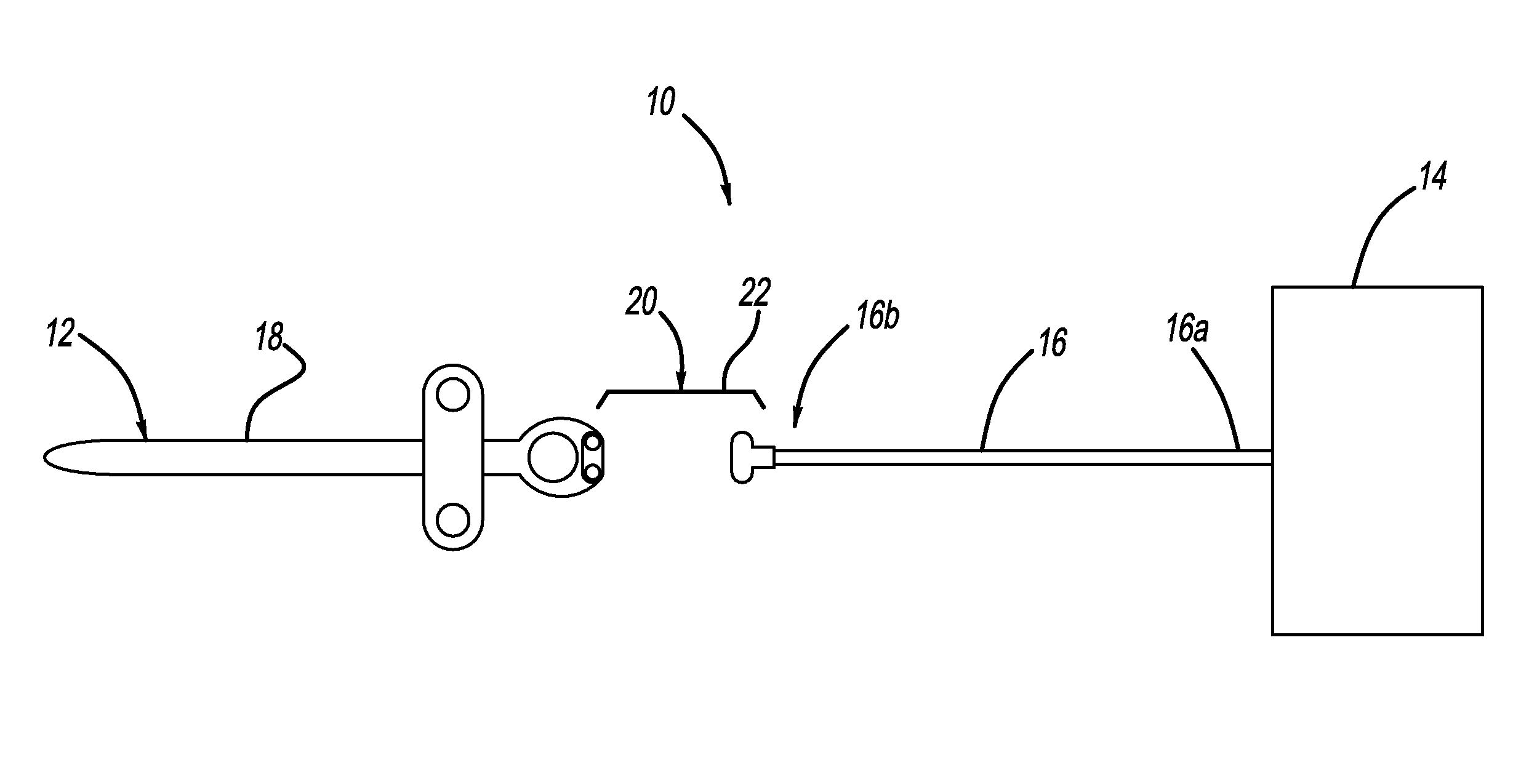
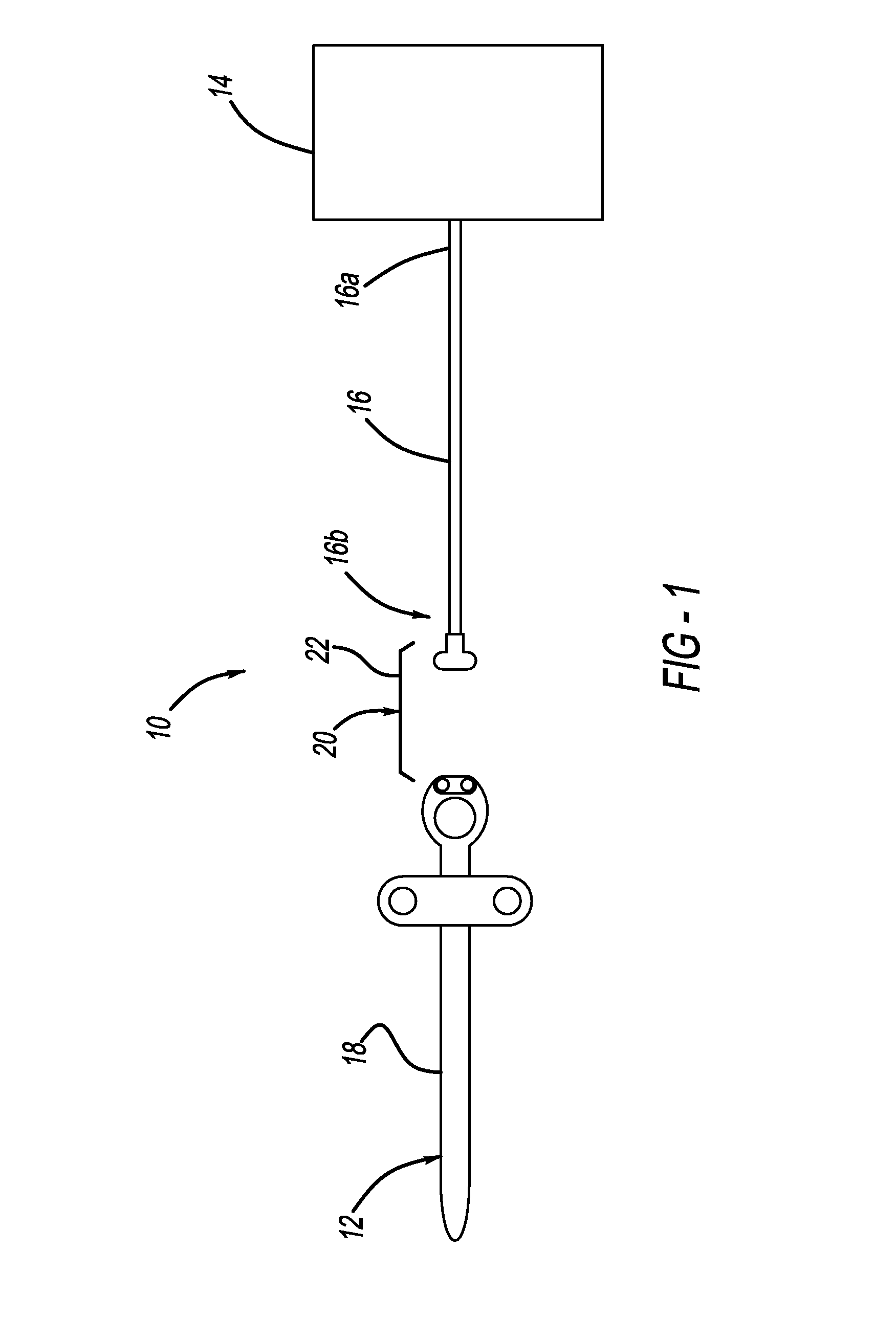
[0040]Referring now to the drawings, FIG. 1 illustrates an electrosurgical system 10 including an electrosurgical device 12, a power source 14, and an electrical cord or power cord 16 connecting the device 12 and the power source 14. In one form, the electrosurgical device 12 is in the form of a sphincterotome 18.

[0041]The electrical cord or power cord 16 can generally include a proximal end 16a that is connected to the power source 14 and a distal end 16b that is connected to the sphincterotome 18. The cord 16 can be connected to the sphincterotome 18 via an electromechanical connection 20. The electromechanical connection 20 can be in the form of a magnetic connection 22, which will be further described below.

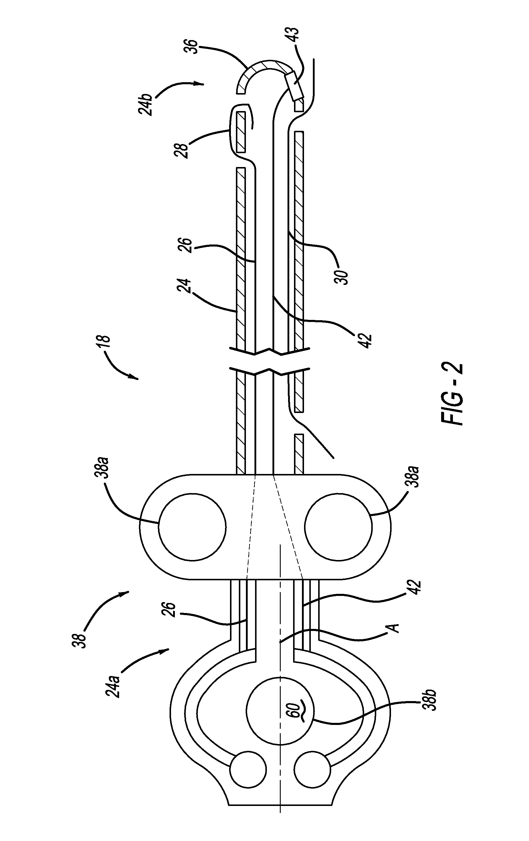
[0042]With reference now to FIG. 2, the sphincterotome 18 includes a tubular body 24 having a proximal end 24a and a distal end 24b. The tubular body 24 includes a cutting wire 26 extending therethrough, where a cutting portion 28 of the cutting wire 26 extends outside of the...


PUM


Abstract

A system for providing current to perform a surgical procedure includes an electrosurgical device having a conductive cutting wire and a power source with a power cord providing current to the cutting wire from a power source. The power cord and device are connected via a magnetic connection. The magnetic connection includes a device housing coupled to a cord housing, where a magnetic post is received in a recess for mechanically and electrically connecting the cutting wire and an active wire of the power cord. The recess and the magnetic post can be coaxial, with the axes being perpendicular to longitudinal axes of the device housing and the cord housing so that the connection can withstand a force exerted along the longitudinal axis, but a sufficient force transverse to the longitudinal axes and along the axes of the recess and the post can de-couple the magnetic connection.

Description

BACKGROUND[0001]1. Field of the Invention[0002]The present embodiments relate generally to a system for providing electrosurgery using electrosurgical devices and, more particularly, to an electrosurgical device having a magnetic connection for transmitting power to the electrosurgical device from a power source.[0003]2. Description of Related Art[0004]The use of electrosurgical devices to perform medical procedures on a patient is common in the medical field. One type of electrosurgical device is a sphincterotome. Sphincterotomes are commonly used to incise or cut a sphincter of a patient. A sphincter is a generally circular muscle that generally maintains constriction of a natural body passage or orifice. A surgeon can operate a sphincterotome to cannulate various ductal systems that include sphincters, such as the biliary duct.[0005]Common sphincterotomes includes structure for navigating through the patient's body to a location where cannulation of the sphincter is desired. The ...

Claims


Application Information

Patent Timeline
Patent Type & Authority Patents(United States)
IPC IPC(8): A61B18/18A61B18/14H01R11/30A61B18/00
CPCA61B18/18A61B18/1492H01R11/30A61B2018/00178A61B2018/00535A61B2018/00553A61B2018/00601A61B2018/144H01R2201/12
Inventor SIGMON, JR., JOHN C.
Owner COOK MEDICAL TECH LLC
Why Eureka
Try Eureka