Electric steering column lock system

a technology for steering column locks and electric steering, which is applied in the field of locking devices for motor vehicles, can solve the problems of inability to overcome the latching device by interruption, and the vulnerability of the conventional locking device to theft attacks

Active Publication Date: 2016-10-25
NISSAN MOTOR CO LTD
View PDF11 Cites 3 Cited by
  • Summary
  • Abstract
  • Description
  • Claims
  • Application Information

AI Technical Summary

Benefits of technology

[0006]One or more embodiments of the present invention improves the steering wheel locking devices of vehicles, especially to improve the security against theft.
[0008]Using the combination of a latching element and an activation mechanism, initiated by manipulating the housing and / or the worm wheel cover of the locking device a high security standard is achieved. Since a third party with thief intention is manipulating the housing and / or the worm wheel cover by moving or deformation or destruction the activation mechanism initiates the latching element to latch the blocking bolt of the locking device and so the blocking bolt is prevented for undesired release.
[0012]In one or more embodiments of the present invention, the latching element is a pin, engaging an opening provided in the blocking bolt. By this direct engagement of the pin into the opening the blocking bolt is latched very effective and any misuse of the locking device is avoided.
[0018]According to one or more embodiments of the present invention, advantageously, the pushing element comprises a spring or is a spring. This is a simple possibility to achieve a “trap function” which can be maintained in tense condition with a long duration of live without tiredness.

Problems solved by technology

Conventional locking devices may be vulnerable to theft attacks.
For this reason, the latching device may not be overcome by interruption of any electric control circuit or the like.
Since the latching element is in interaction immediately with the blocking bolt there is no way to compass the latching system by destroying intermediate elements, because there are no intermediate elements between the latching element and the blocking bolt.

Method used


Image

  • Electric steering column lock system
  • Electric steering column lock system
  • Electric steering column lock system

Examples


Embodiment Construction

[0026]Embodiments of the invention will be described below with reference to the drawings. In embodiments of the invention, numerous specific details are set forth in order to provide a more thorough understanding of the invention. However, it will be apparent to one of ordinary skill in the art that the invention may be practiced without these specific details. In other instances, well-known features have not been described in detail to avoid obscuring the invention.

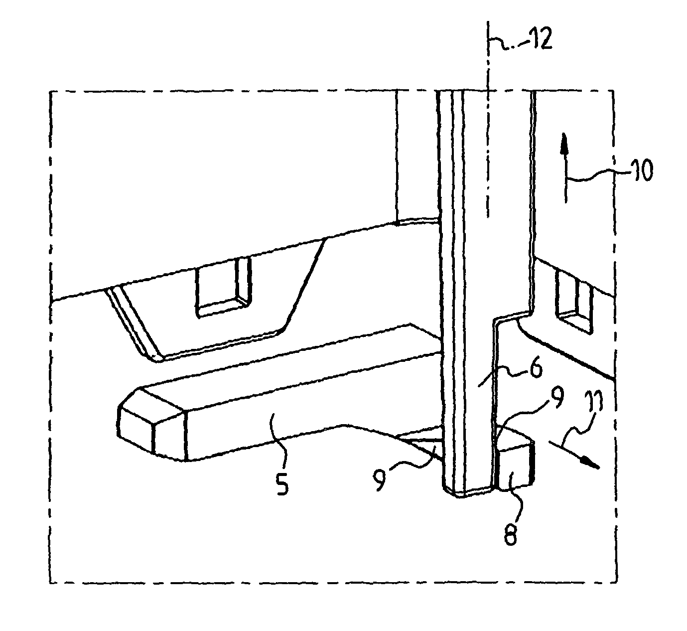
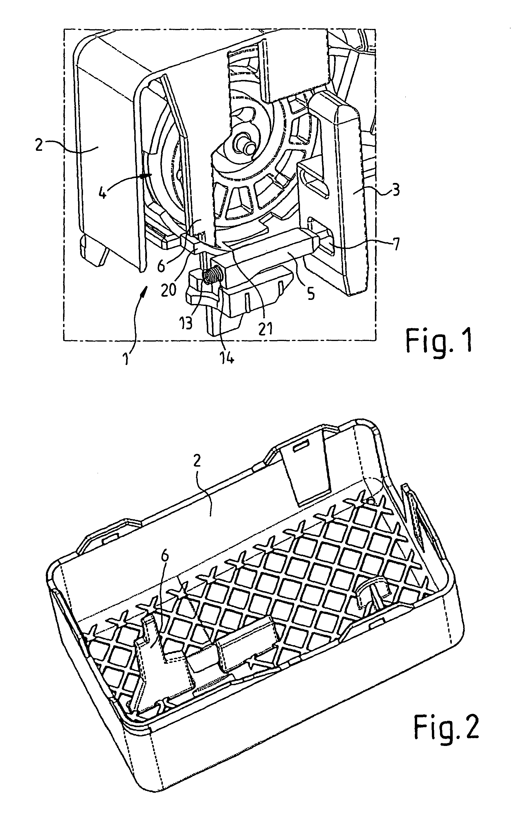
[0027]In perspective representation according to FIG. 1 the locking device 1 and parts of the housing 2 are shown. The blocking bolt 3 is drawn without its holding and guiding element. The blocking element 3 is driven by a drive 4 in form of a worm wheel. A latching pin 5 is arranged in front of an opening 7 in the blocking bolt 3. A trigger element 6 is in contact with the face of contact 9 of the latching pin 5 during the regular operation mode (see FIG. 3). The arrows 10 and 11 in FIG. 3 illustrate two directions of ...


PUM


Abstract

A locking device for a motor vehicle having a steering wheel column has a housing, a worm wheel cover, a blocking bolt that locks a steering wheel shaft in the steering wheel column, wherein the blocking bolt is movable between a first and a second position, a drive that moves the blocking bolt from the first position to the second position, a latching element that latches the blocking bolt, a mechanical activation mechanism that activates the latching element, and that has a trigger element, and a pushing element. In the first position, the blocking bolt is in blocking engagement with the steering wheel shaft. In the second position, the blocking bolt is disengaged from the steering wheel shaft. The latching element comprises a pin, and an opening is disposed in the blocking bolt for engagement with the pin.

Description

BACKGROUND[0001]1. Technical Field[0002]The invention relates to a locking device for a motor vehicle.[0003]2. Related Art[0004]Conventional locking devices in this technical field for motor vehicles usually have a blocking bolt, which is movable between a first and a second position for locking the steering wheel shaft in the steering wheel column. In the first position the blocking bolt can be brought into blocking engagement with the steering wheel shaft and in the second position the blocking bolt is disengaged from the steering wheel shaft. The locking device furthermore usually has a drive to move the blocking bolt, which is located in a housing. The blocking bolt is part of the steering wheel column and is integrated in particular in the steering wheel column. For example such a blocking device is described in the WO 2011 / 104017 A1. DE 102 47 803 B3 discloses a locking device that includes a latching device for latching the blocking device, that is sensitive to manipulation o...

Claims


Application Information

Patent Timeline
Patent Type & Authority Patents(United States)
IPC IPC(8): B60R25/0215
CPCB60R25/02153B60R25/0215B62D1/184E05B81/02
Inventor MARX, THILOVAGNEY, DAMIENHAYASHI, KENJIROU
Owner NISSAN MOTOR CO LTD
Why Eureka
Try Eureka