
Apparatus, method, and system for LED fixture temperature measurement, control, and calibration

a technology of led fixture and temperature measurement, applied in the field of large-area lighting, can solve the problems of reducing the life expectancy or premature failure of the fixture, delivering as much light, and reducing the lumen output of the fixture, so as to improve the state of the art

Active Publication Date: 2016-10-25
MUSCO
View PDF51 Cites 0 Cited by
  • Summary
  • Abstract
  • Description
  • Claims
  • Application Information

AI Technical Summary

Benefits of technology

The patent discusses a system for controlling the performance of LED lighting circuits. The system uses both open-loop and closed-loop control strategies to achieve desired results such as controlling failure, adjusting current to control temperature, increasing efficiency, etc. The technical effect of this system is to provide better control and performance optimization for LED lighting circuits.

Problems solved by technology

During this elapsed time period, as junction temperature increases, output lumens per input watt decrease, which normally results in decreased fixture lumen output, since LED drivers typically provide a constant current level regardless of ambient temperature or LED temperature.
Conversely, a light being operated in warmer ambient conditions will initially not deliver as much light, and will not take as long to reach thermal equilibrium.
However in high ambient temperatures, and for LEDs operated at relatively high power levels, there is a risk of operating at an unacceptably high junction temperature, which can result in decreased life expectancy or premature failure.
Furthermore, LEDs experience lumen loss, which is a gradual reduction over time in their ability to produce light.
Lumen loss is greater when LEDs are operated at higher temperatures and at higher currents.
LED manufacturers typically provide information about an LED product only under limited operating conditions.
However, this introduces additional components into the operating circuit which can make it more difficult to observe LED operational status.

Method used


Image

  • Apparatus, method, and system for LED fixture temperature measurement, control, and calibration
  • Apparatus, method, and system for LED fixture temperature measurement, control, and calibration
  • Apparatus, method, and system for LED fixture temperature measurement, control, and calibration

Examples


embodiment one

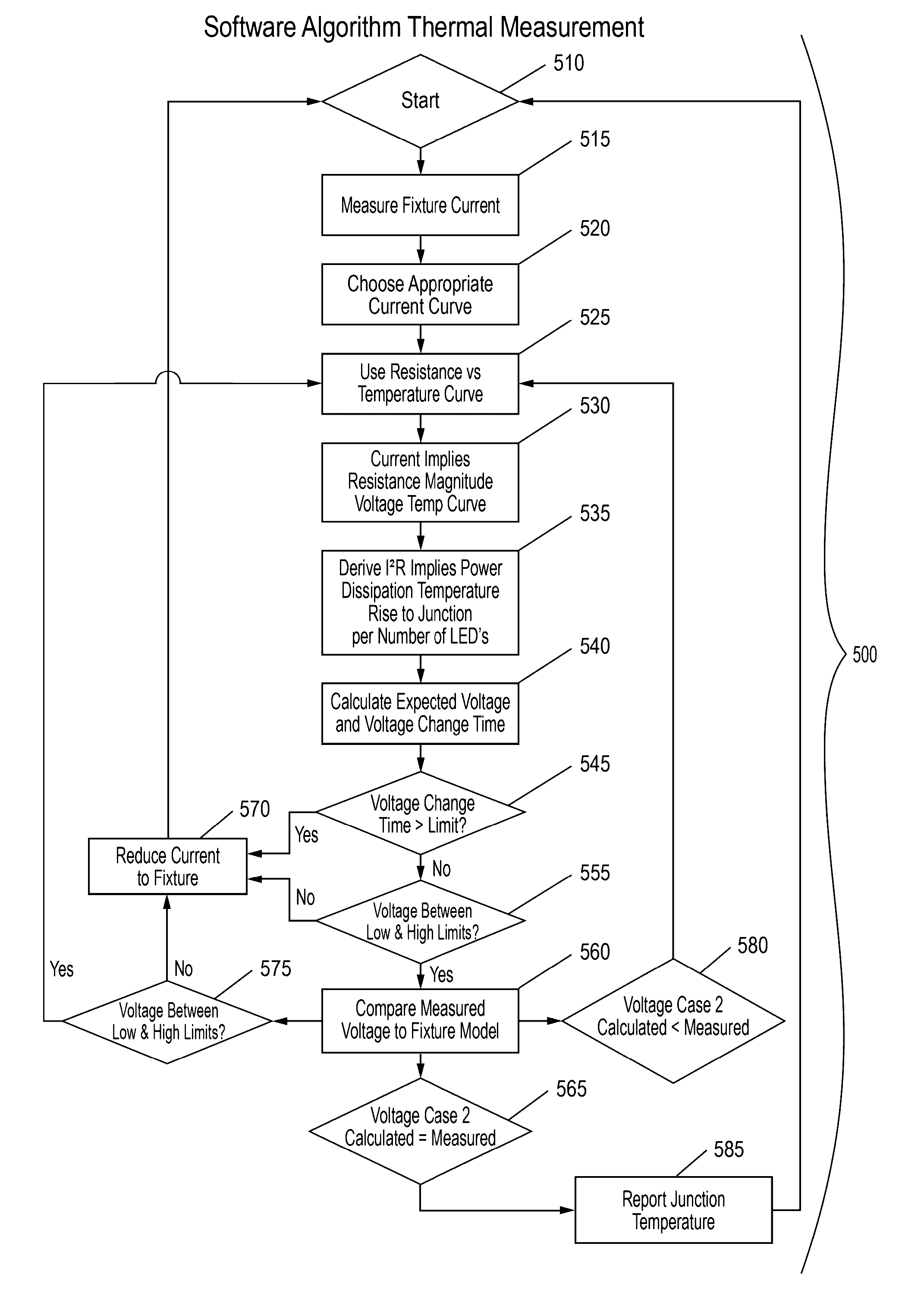
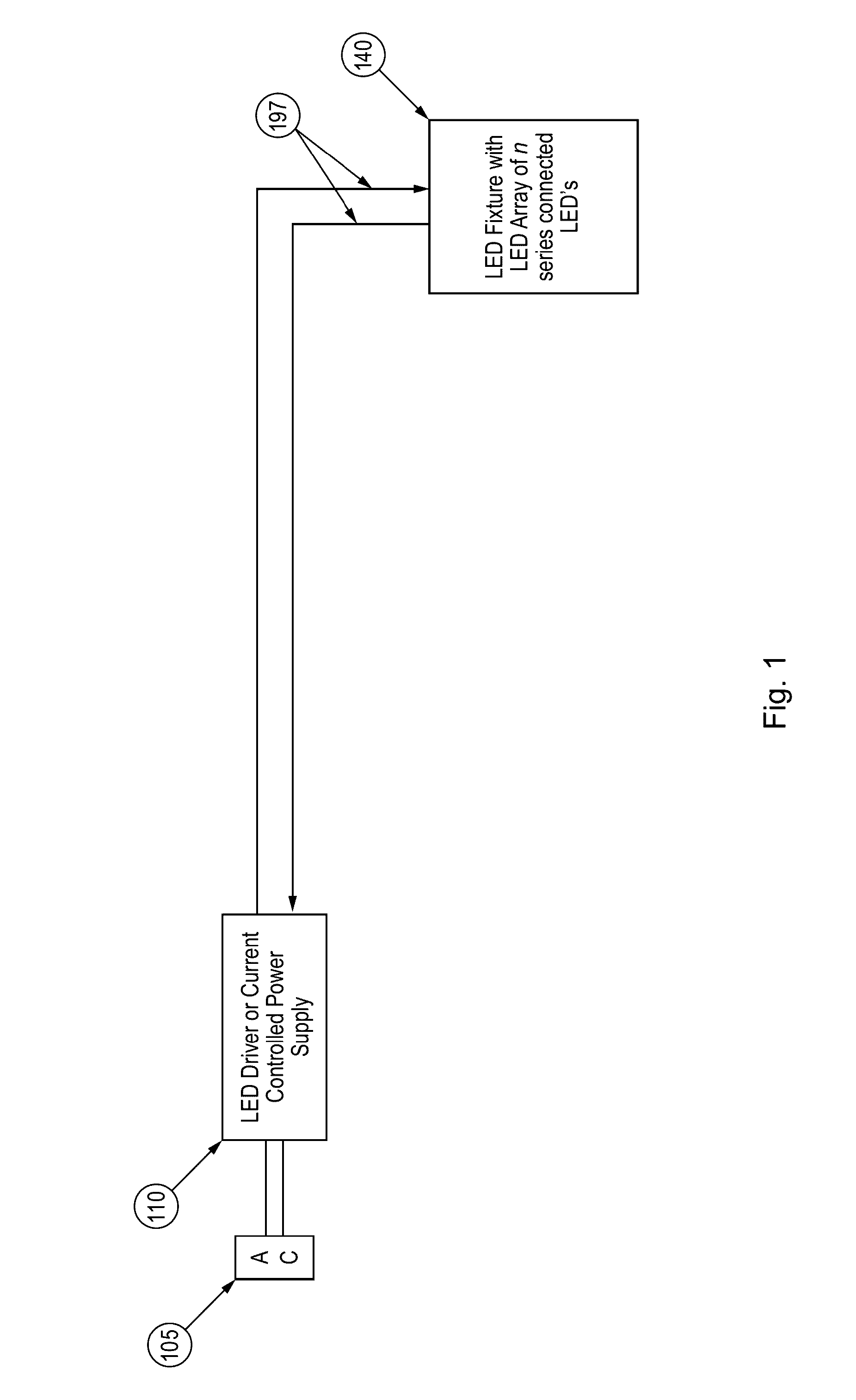
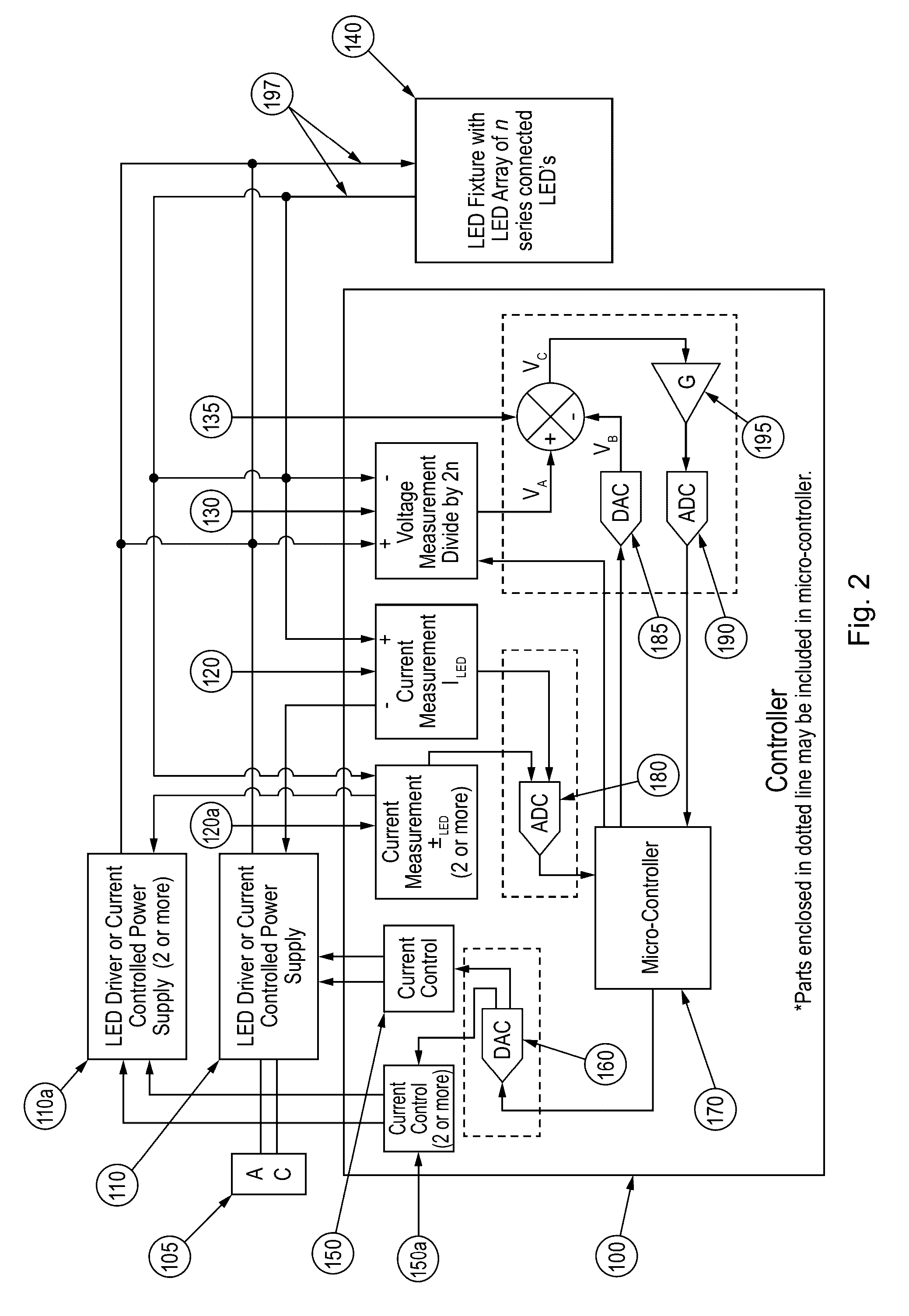
[0100]An embodiment according to aspects of the invention comprises a printed circuit board “controller” with attached components as illustrated in FIGS. 8 and 9. The controller includes four separate I / O channels for four separate fixtures or strings of LEDs using four separate current drivers.

[0101]Current and control channels are input at connectors 1-4, FIG. 8, from separate LED controllers such as the LED Driver Model TRC-100S105DT available from Thomas Research Products (11548 Smith Drive, Huntley, Ill. 60142). Current to LED fixtures or strings is output at connectors 5-8. Optional 12V input may be supplied at connector 9 and 10. AC current is input at connector 11. A temperature monitor 20 is provided to supply information that may be desired about temperature of the controller and external temperatures such as ambient temperature. Temperature sensors may be connected to the controller board via connectors 15, FIG. 8. Communications links are provided at connectors 12-13, FI...


PUM


Abstract

The present invention generally relates to the field of large area lighting, such as lighting for sport venues. More specifically, some embodiments of the present invention relate to controlling solid state illumination for various applications including sports lighting, architectural lighting, security lighting, parking, general area, interior, larger area and others. Embodiments according to aspects of the current invention monitor lighting circuits with regard to voltage and current, compare readings with stored models, characterize lighting circuits with regard to stored models for voltage and current, and control lighting circuits in accordance with desirable outcomes.

Description

CROSS-REFERENCE TO RELATED APPLICATIONS[0001]This application claims priority under 35 U.S.C. §119 to provisional application Ser. No. 61 / 404,291 filed Sep. 30, 2010, herein incorporated by reference in its entirety.I. BACKGROUND OF THE INVENTION[0002]The present invention generally relates to the field of large area lighting, such as lighting for sport venues. More specifically, some embodiments of the present invention relate to controlling solid state illumination for various applications including sports lighting, architectural lighting, security lighting, parking, general area, interior, larger area and others.[0003]LED lighting has many potential advantages for use in large area lighting. These benefits may include long life, efficient lighting, high intensity lighting, variability, etc. Optimizing these benefits is one goal of the lighting designer which would be facilitated by being able to measure operational status of LEDs.[0004]Several known conditions affect normal LED o...

Claims


Application Information

Patent Timeline
Patent Type & Authority Patents(United States)
IPC IPC(8): H05B37/02H05B33/08H05B44/00
CPCH05B33/0872H05B33/0866H05B37/02H05B33/0851H05B33/0854H05B45/14H05B45/10H05B45/56H05B47/175
Inventor BLANCHARD, DAVID L.SCHEMBS, ANDREW J.SHELDON, ALAN W.
Owner MUSCO
Learn More