Packaging for a catheter

a catheter and packaging technology, applied in the field of catheters, can solve the problems of re-closure of the dilated vessel or even perforation of the vessel wall, damage to one or both, and inability to fully cover the opening in the tubing, etc., and achieve the effect of facilitating insertion and removal of the catheter

Active Publication Date: 2016-11-15
MEDTRONIC VASCULAR INC
View PDF13 Cites 0 Cited by
  • Summary
  • Abstract
  • Description
  • Claims
  • Application Information

AI Technical Summary

Benefits of technology

[0006]Embodiments hereof relate to a packaging device for a catheter having an elongated shaft and a proximal luer. The packaging device includes a coiled tube defining a lumen configured to receive the elongated shaft of the catheter, and a substantially planar mounting card coupled to the coiled tube. The mounting card includes an integral moveable luer retainer configured to selectively alternate between a first configuration which secures the proximal luer of the catheter within an opening formed on the luer retainer and a second configuration which releases the luer from the opening on the luer retainer and eases insertion and removal of the catheter. The mounting card may also include an integral support flap that folds over a proximal segment of the coiled tubing and creates a generally triangular contact zone to press when removing the elongated shaft of the catheter from the coiled tube. The mounting card may also include a sinusoidal cut which forms at least one integral tab for attaching an accessory bag thereto.

Problems solved by technology

Dilation of an occlusion, however, can form flaps, fissures, and dissections, that may result in re-closure of the dilated vessel or even perforations in the vessel wall.
However, by grasping the proximal end of the hoop, the opening in the tubing may become misshapen due to pressure from the fingers of the operator.
Accordingly, when the balloon and / or stent attempt to pass through the opening, one or both may become damaged.
Such damage may be especially problematic with coated stents which are now popular.

Method used


Image

  • Packaging for a catheter
  • Packaging for a catheter
  • Packaging for a catheter

Examples


Embodiment Construction

[0026]Specific embodiments of the present invention are now described with reference to the figures, wherein like reference numbers indicate identical or functionally similar elements. The terms “distal” and “proximal” are used in the following description with respect to a position or direction relative to the treating clinician. “Distal” or “distally” are a position distant from or in a direction away from the clinician. “Proximal” and “proximally” are a position near or in a direction toward the clinician.

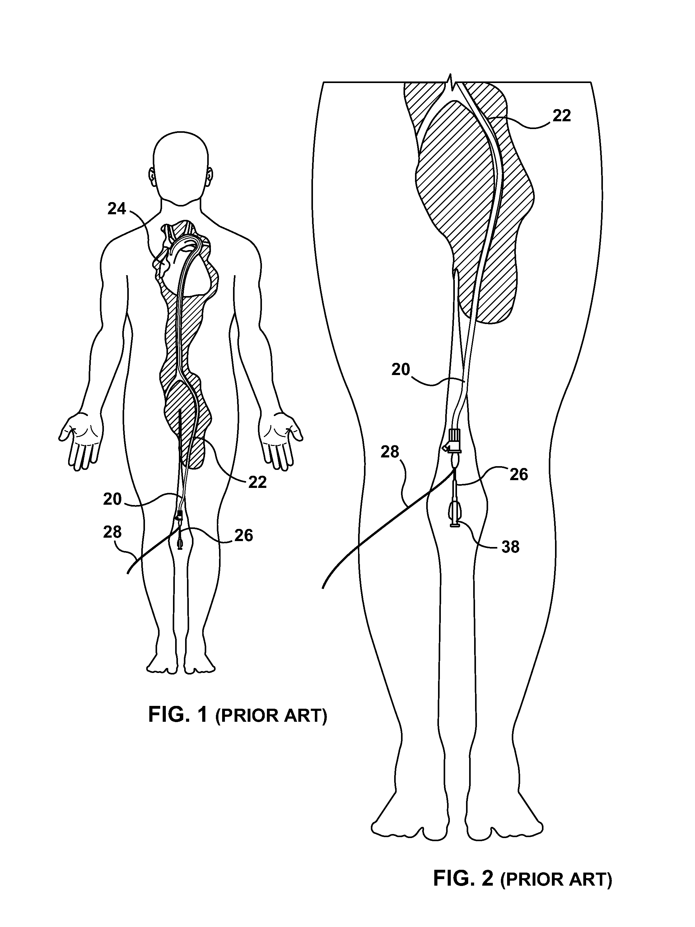
[0027]As stated previously, to treat small diameter vessels remote from an entry point into a patient, a guiding catheter may be used to span the distance. For example, FIGS. 1 and 2 illustrate the deployment of a balloon catheter within a patient's vasculature. In PTCA or stent delivery, a guiding catheter 20 is typically inserted into a large artery 22 near the patient's groin and is then advanced towards heart 24 to the entry opening or ostium of a diseased coronary artery. G...


PUM


Abstract

Packaging for a catheter includes coiled tubing for receiving the catheter and a mounting card coupled to the coiled tubing. The windings of the coiled tubing are welded together to maintain the coiled configuration. The mounting card includes an integral support flap for reducing the risk of damage during catheter insertion and removal, an integral luer retainer for securing a catheter luer, and one or more integral tabs for attaching catheter accessories to the packaging. The integral support flap creates a contact zone which discourages grasping the packaging at a location that can potentially damage an object passing through the packaging, such as a balloon and / or stent. The integral luer retainer is configured to selectively alternate between a configuration which secures the catheter luer and configuration which allows releases the luer for easy insertion and removal of the catheter.

Description

FIELD OF THE INVENTION[0001]The present invention relates generally to catheters intended for deployment within a patient's vasculature, and more particularly, to packaging for a catheter.BACKGROUND OF THE INVENTION[0002]Catheters may be inserted into a patient's vasculature and deployed at various locations within the patient for a wide variety of purposes and medical procedures. For example, one type of catheter is used in percutaneous catheter intervention (PCI) for the treatment of a vascular constriction generally known as a stenosis. In this instance, the catheter has a distally mounted balloon that can be placed, in a deflated or collapsed condition, within the stenosis, and then inflated or expanded to dilate the narrowed lumen of a blood vessel. This type of balloon dilation therapy is generally referred to as percutaneous transluminal angioplasty (PTA). When the treatment is more specifically intended for vessels of the heart, the process is known as percutaneous translumi...

Claims


Application Information

Patent Timeline
Patent Type & Authority Patents(United States)
IPC IPC(8): A61M25/00
CPCA61M25/002
Inventor LIMJAROEN, PAWEENAMORRIS, THEODOREKIEFER, AMANDA
Owner MEDTRONIC VASCULAR INC
Why Eureka
Try Eureka