These items do not fit in conventional drawers and are often stored on end in a corner of the room leaning against a wall, in a
barrel of some type, on a wall rack, or on hooks.
All of these storage methods have significant disadvantages.
For example, rakes and brooms do not fit well in the corner in an inverted vertical position and are unstable when simply stood against the wall.
A stack of elongate tools standing on end is prone to sliding and falling, creating both
clutter and a safety
hazard.
Additionally, when the number of tools stored in such a way increases, retrieving an item becomes difficult because it is often necessary to disassemble the entire stack to get to the desired tool, and then reassemble the stack.
Similarly, storing tools in a heap on the floor complicates retrieval, creates
clutter, and takes up a substantial amount of space.
While hanging tools from hooks or supports attached to a wall is a space-saving method, which advantageously permits tools to be organized, a number of practical limitations and disadvantages arise.
This complicates the use of such supports, especially when multiple users remove several tools simultaneously.
This often leads to returning the tools to the wrong holders, which in turn leads to disorganized and unsafe storage of the tools.
Additionally, placement and removal of tools from wall-mounted supports can require some amount of skill and precision.
Similarly, when the stored tools are intended for use by multiple users of substantially different height, strength, and arm reach, as it is often the case in households with
small children or elderly family members, it is difficult to choose a location for the supports on the wall which is both convenient and safe for all users.
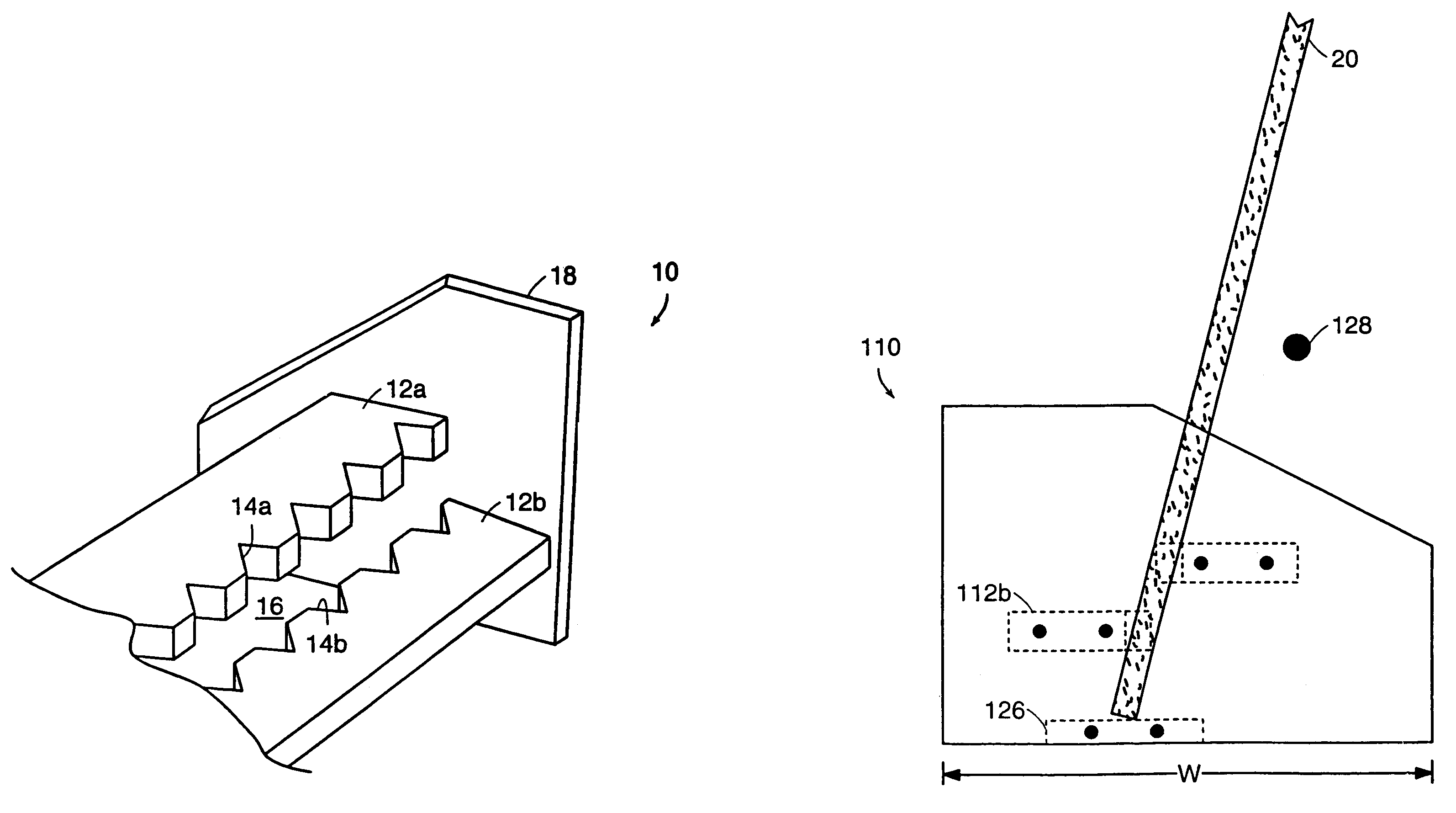
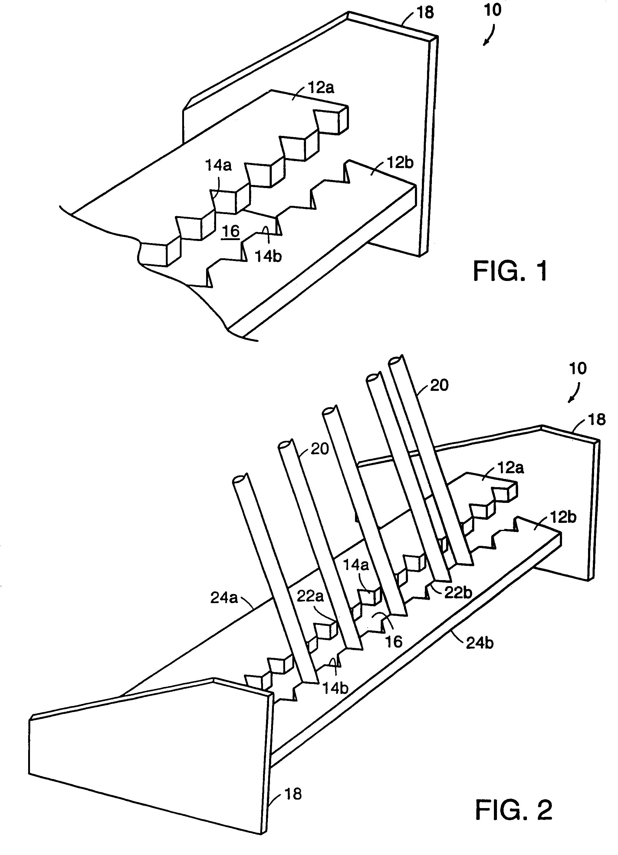
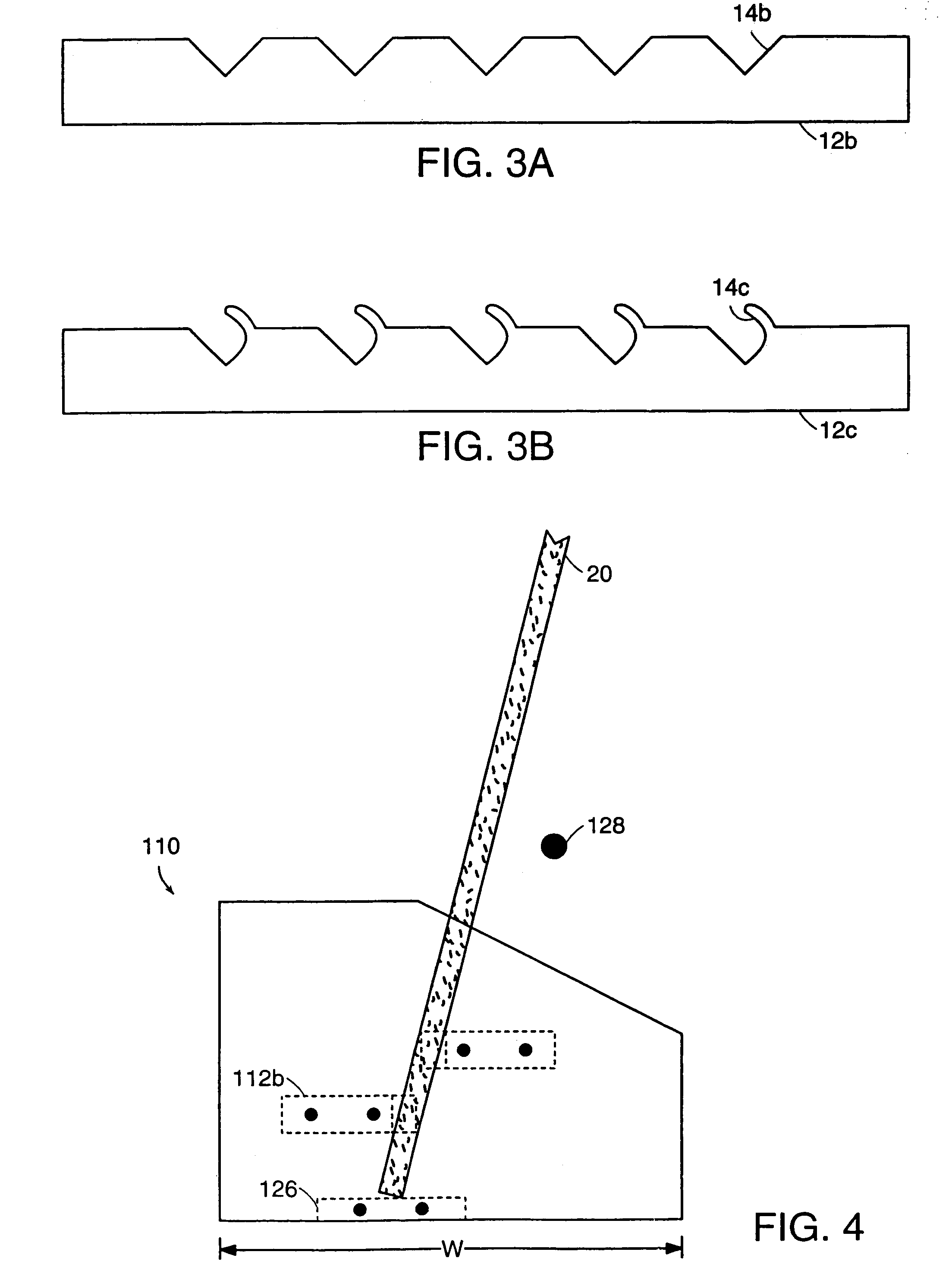
Storage of tools that do not have any openings or protuberances present a problem as they do not possess any means for readily holding the tool in the support; thus, they simply cannot be safely stored on hooks or other wall-mounted supports.
Lastly, any generally linear arrangement of hooks or supports can also be problematic in that, unless staggered vertically or widely separated horizontally, tool heads can overlap, making removal difficult or requiring removal of more than one tool to access the tool of choice.
Many of these tool organizers known in the art have a bulky body with a substantial
footprint.
Such a configuration renders these organizers difficult to use in confined spaces, such as between a garage wall and a car, or between cars.
Additionally, some organizers limit the ability of the user to organize the tools as desired, because the organizer may have a certain number of specific mounts or locations designed for particular types of tools.
This complicates the use of such organizers by limiting the number of locations a particular tool may be returned to and often leads to disorganization.
Finally, many of the organizers known in the art require substantial lifting of tools in order to insert or remove them from the organizer.
This complicates and often prohibits using such organizers in
low overhead environments, as well as by children and the elderly.

