
Multi-element storage array

Active Publication Date: 2005-08-02
ORACLE INT CORP
View PDF35 Cites 29 Cited by
  • Summary
  • Abstract
  • Description
  • Claims
  • Application Information

AI Technical Summary

Benefits of technology

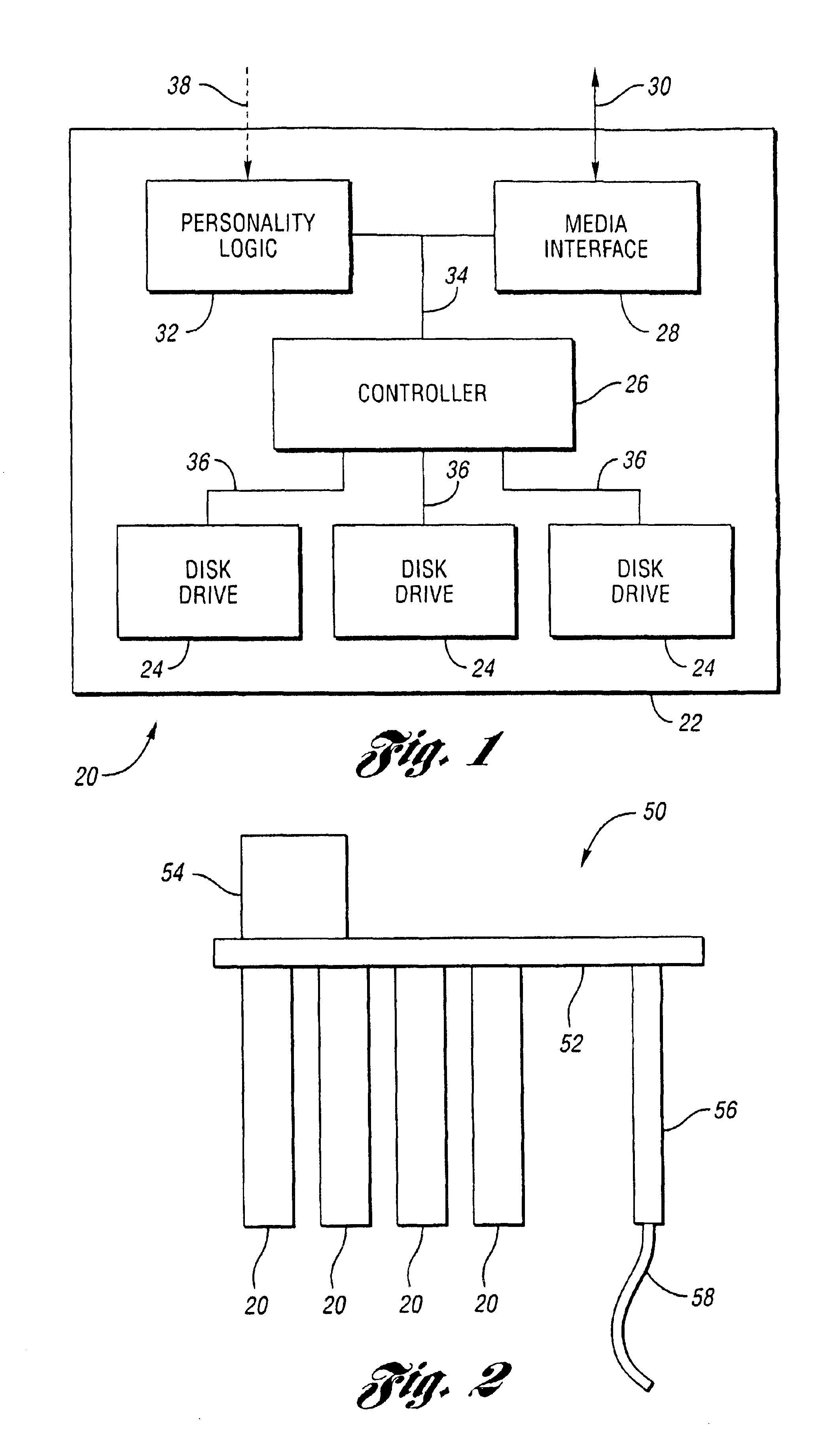
[0009]The present invention fulfills the need for intermediate storage with performance characteristics similar to high performance disk systems as well as cost and density characteristics comparable to tape systems. Storage assemblies include programmable logic allowing each assembly to appear as a wide variety of different storage devices. The present invention includes data storage assemblies having multiple data storage units, such as disk drives or other data storage devices, co-located onto a replaceable assembly. In one embodiment, multiple storage assemblies are integrally connected to a single chassis for ease of hot plug insertion and removal.
[0010]The present invention provides for scalable and incremental increase of storage capacity and performance. The modular design provides for sharing of power and cooling facilities, thus reducing product cost and simplifying manufacturing and reliability. The ability to work with any high performance data storage interface allows data storage units to be utilized to maximum potential. Data storage units, such as ATA disk drives, are connected within small groups so that aggregate performance and functional capabilities can be combined into a higher performing complete storage assembly.
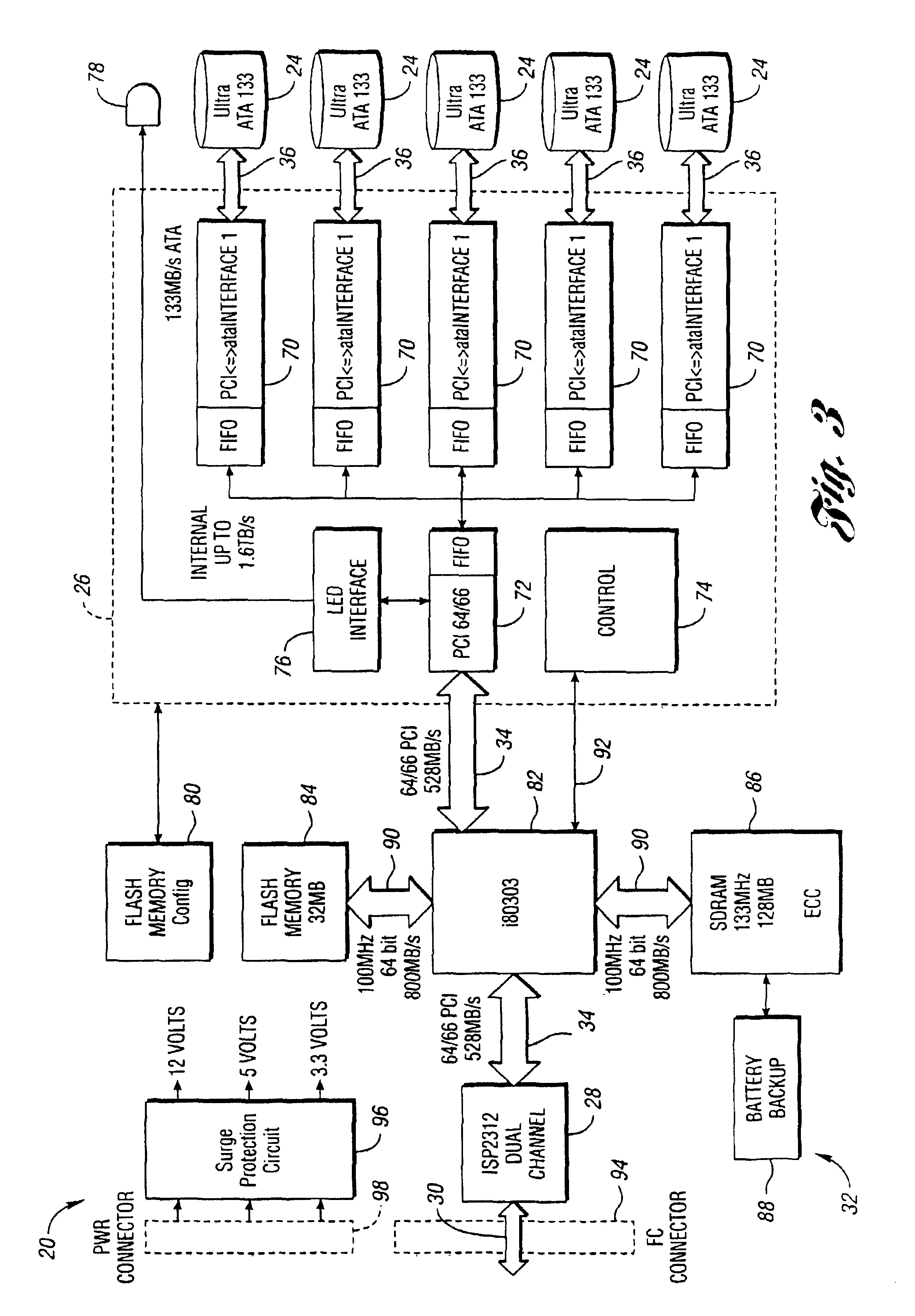
[0011]In one embodiment of the present invention, each module contains five ATA disk drive assemblies. Individual data storage assemblies contain control electronics and a data connection interface which presents and emulates the electrical image of a single disk drive, tape drive, tape library or the like for connection to industry standard FC interfaces. These modules may be held in a single chassis. An implementation with ten modules contains a total of fifty individual disk drives, providing a high performance architecture that aggregates benefits of the individual disk drives in a very condensed package. This architecture also provides a compact means of providing a high capacity, high band width data storage solution at minimal production cost. This architecture also integrally contains sufficient modularity to provide scalable storage capacity with new assemblies. New generation disk storage capacity or other technologies may easily be incorporated into the modular assemblies to provide increased flexibility in product implementation.

Problems solved by technology

However, an increasing amount of data must be stored for extended periods of time.
Long term data storage must often meet apparently conflicting performance criteria.
Traditionally, no one type of storage device has been able to satisfy cost, speed, density and reliability requirements.
High performance magnetic disks have been used as a first level of data storage due to their high data rates and low access times. However, high performance magnetic disk systems tended to be relatively expensive and low density.
Magnetic tape offered greater storage density and lower cost-per-bit than high performance magnetic disk systems, but often suffered from greatly increased data access time.
Various attempts at providing an intermediate level of long term storage have not met with great commercial success.
However, implementing groups or arrays of these inexpensive, low performance disks exhibit certain difficulties.
For example, inexpensive disks are typically incompatible with high speed media interfaces such as Fibre Channel (FC), SCSI, iSCSI, ESCON and the like.
Another problem with arrays of inexpensive disks is that such arrays tend not to provide any increase in storage density over high performance disk systems.
Yet another problem with arrays of inexpensive disks is that such arrays are typically designed for special purpose use only and are not compatible or configurable for use with a large number of high performance computer interfaces or applications.

Method used


Image

  • Multi-element storage array
  • Multi-element storage array
  • Multi-element storage array

Examples


Embodiment Construction

)

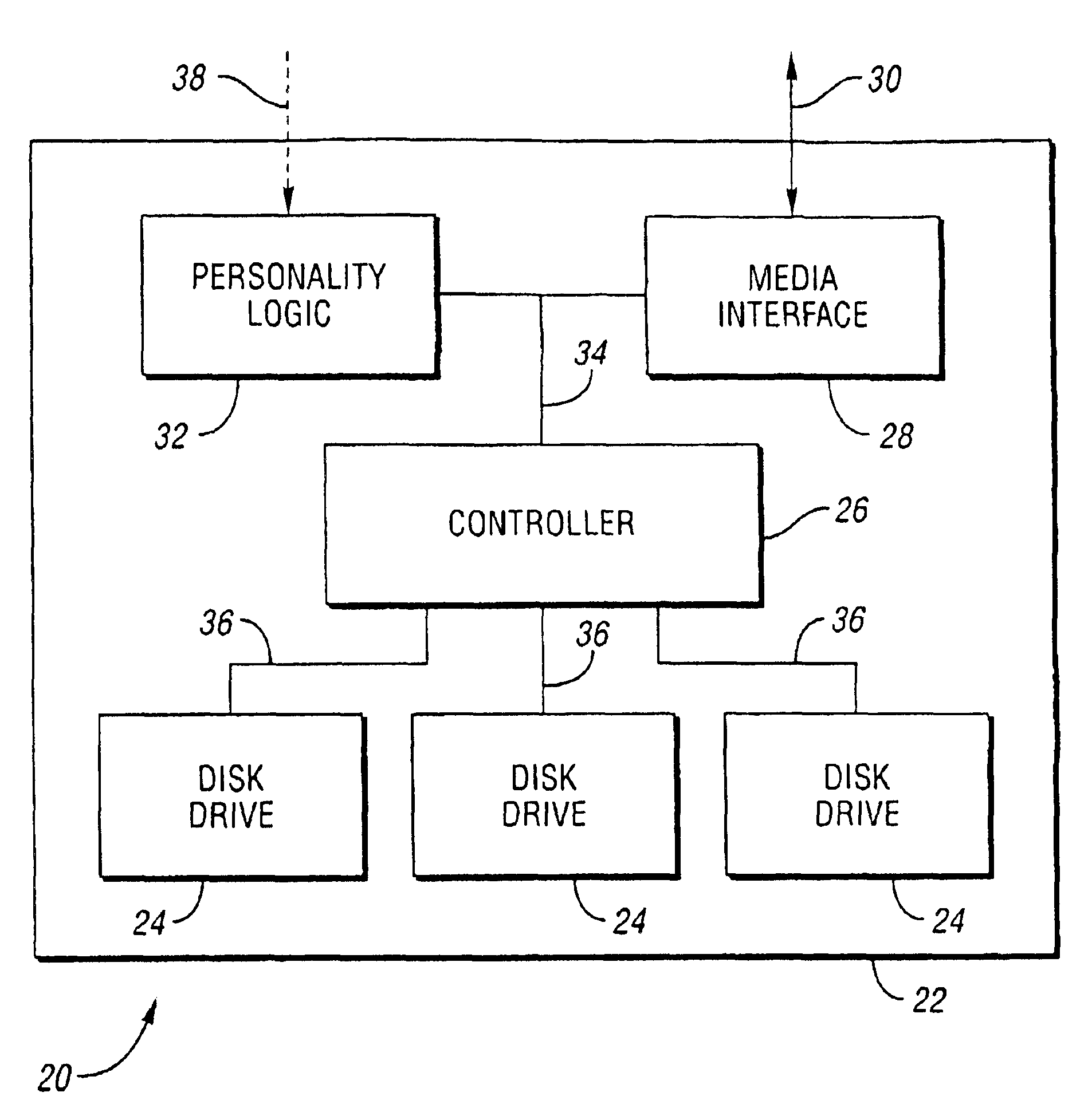
[0035]Referring now to FIG. 1, a data storage module according to an embodiment of the present invention is shown. A data storage module or blade, shown generally by 20, includes printed circuit board 22. Multiple storage units such as disk drives 24 are affixed or coupled to printed circuit board 22. Controller 26 is mounted on printed circuit board 22. Controller 26 receives data access commands, writes data to storage units 24 based on the received commands and reads data from storage units 24 based on the received commands. Media interface 28 is also mounted on printed circuit board 22. Media interface 28 communicates over interconnection media 30 in a format compatible with interconnection media 30. Personality logic 32 is also mounted on printed circuit board 22. Personality logic 32 provides a programmable personality causing data storage module 20 to appear over media 30 as a kind of storage device different than storage modules 24.

[0036]Media 30 interfacing data storage mo...


PUM


Abstract

A self-contained data storage module receives a data request conforming to a first standard. The data request is translated into a second standard. At least one of the storage devices mounted on a board within the data storage module is identified. The translated data request is transmitted to each identified storage device, where the data request is serviced.

Description

CROSS-REFERENCE TO RELATED APPLICATIONS[0001]This application claims the benefit of U.S. provisional application Ser. No. 60 / 395,055, titled “Multi-Element Storage Array,” filed Jul. 11, 2002, which is herein incorporated by reference in its entirety.BACKGROUND OF THE INVENTION[0002]1. Field of the Invention[0003]The present invention relates to data storage systems.[0004]2. Background Art[0005]Greater quantities of data are being generated and stored by computer systems. Some data, such as intermediate calculations, is discarded almost immediately. However, an increasing amount of data must be stored for extended periods of time. This period of time may range from minutes to years depending on the type of data, type of application which generates or uses the data, and requirements imposed by government regulations, business practices, historical needs, and the like.[0006]Long term data storage must often meet apparently conflicting performance criteria. Ideally, all storage should ...

Claims


Application Information

Patent Timeline
IPC IPC(8): G06F3/06G11B20/18G11B33/12
CPCG06F3/0614G06F3/0626G06F3/0661G06F3/0689G11B20/1833G11B33/125
Inventor KONSHAK, MICHAEL V.FECHNER, JIMMY R.EICHEL, DALE R.KEMMER, LAWRENCE R.SNYDER, MARK S.WEWEL, PAUL A.
Owner ORACLE INT CORP
Learn More