Inter-operative switching of tools in a robotic surgical system

a robotic surgical system and tool switching technology, applied in the field of improved surgical and/or robotic devices, systems, and methods, can solve the problems of system more prone to error, less invasive, and added layers of complexity

Active Publication Date: 2016-11-29
INTUITIVE SURGICAL OPERATIONS INC
View PDF23 Cites 13 Cited by
  • Summary
  • Abstract
  • Description
  • Claims
  • Application Information

AI Technical Summary

Problems solved by technology

However, only a relatively small number of surgeries currently use these techniques due to limitations in minimally invasive surgical instruments and techniques and the additional surgical training required to master them.
The use of different controllers results in added layers of complexity that make the system more prone to error, and may effectively limit the use of new manipulators and / or tools with a preexisting system.

Method used


Image

  • Inter-operative switching of tools in a robotic surgical system
  • Inter-operative switching of tools in a robotic surgical system
  • Inter-operative switching of tools in a robotic surgical system

Examples


first embodiment

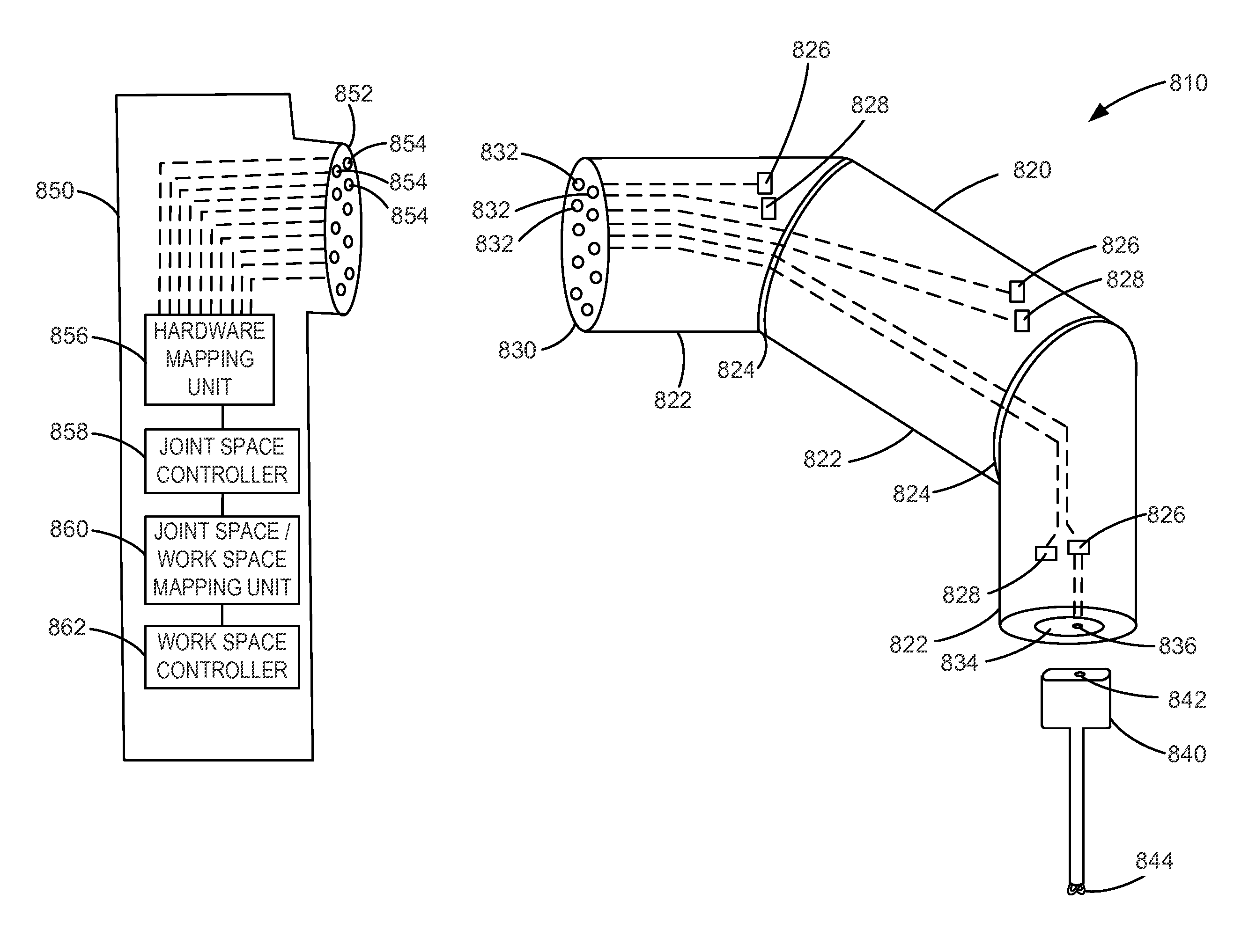
[0105]FIG. 8A is part of a robotic system including a manipulator assembly 810 and a support structure 850 according to a The manipulator assembly 810 includes a manipulator 820 and a tool 840, where the manipulator 820 is disposed between and may be connected to each of the support structure 850 and the tool 840.

[0106]The manipulator 820 includes a plurality of links 822 coupled together by joints 824. The manipulator 820 may also include a number of actuators 826 such as motors, and a number of sensors 828 such as potentiometers, where each joint may be associated with an actuator and / or a sensor. The actuator may be operable to control a degree of freedom of the manipulator, such as by controlling one or more joints to rotate, translate, etc. Further, the sensor may be operable to measure a position or state of each of a corresponding joint.

[0107]The manipulator 820 also includes a connector 830 at a proximal end that is shaped to engage a corresponding connector of the support ...

second embodiment

[0118]FIG. 8B is part of a robotic system including a manipulator assembly 810 and a support structure 850 according to a The manipulator assembly 810 and support structure 850 in this embodiment are similar to that discussed with reference to FIG. 8A, and thus the structures and functions discussed with reference to FIG. 8A are equally applicable for this embodiment.

[0119]In accordance with this embodiment, however, the tool 840 includes an electrical / optical contact 846 coupled to and operable to communicate information with an internal element 848 of the tool 840. The element 848 may be, e.g., an actuator such as actuator 826 and / or a sensor such as sensor 828. The actuator may be operable to control a degree of freedom of the tool 840, and the sensor 828 may be operable to sense a position and / or state of the degree of freedom. For example, the actuator may be operable to control a joint of the tool 840, and the sensor may be operable to sense a position of the joint. In some e...

third embodiment

[0121]FIG. 8C is part of a robotic system including a manipulator assembly 810 and a support structure 850 according to a The manipulator assembly 810 and support structure 850 in this embodiment are similar to that discussed with reference to FIG. 8A, and thus the structures and functions discussed with reference to FIG. 8A are equally applicable for this embodiment.

[0122]The tool 840 in this embodiment includes a tool identification unit 845. The tool identification unit 845 may store a tool identifier that identifies one or more characteristics of the tool. For example, the tool identifier may identify the type of tool (e.g., endoscope, jaws, vacuum, electrosurgical paddle, etc.), the number of degrees of freedom of the tool (e.g., 3 degrees of freedom, 4 degrees of freedom, 5 degrees of freedom, etc.), the types of degrees of freedom (e.g., motion degrees of freedom such as roll, translate, etc., actuation degrees of freedom such as activating a vacuum or electrode, etc.), etc....


PUM


Abstract

Methods, apparatus, and systems for controlling a telesurgical system are disclosed. In accordance with a method, a first tool connected to a first manipulator of the system, and a second tool connected to a second manipulator of the system, are controlled. A swap of the tools such that the first tool is connected to the second manipulator and the second tool is connected to the first manipulator is then detected. The first tool connected to the second manipulator and the second tool connected to the first manipulator are then controlled.

Description

CROSS-REFERENCES TO RELATED APPLICATIONS[0001]The present application claims the benefit under 35 USC 119(e) of U.S. Provisional Application No. 61 / 793,227 filed Mar. 15, 2013. The full disclosure of which is incorporated herein by reference in its entirety for all purposes.[0002]The present application is generally related to the following commonly-owned applications: U.S. Provisional Application No. 61 / 683,495, filed Aug. 15, 2012, entitled “Phantom Degrees of Freedom for Manipulating the Movement of Robotic Systems”, U.S. Provisional Application No. 61 / 654,764 filed Jun. 1, 2012, entitled “Commanded Reconfiguration of a Surgical Manipulator Using the Null Space”, U.S. application Ser. No. 12 / 494,695 filed Jun. 30, 2009 (Allowed), entitled “Control of Medical Robotic System Manipulator About Kinematic Singularities;” U.S. application Ser. No. 12 / 406,004 filed Mar. 17, 2009 (now U.S. Pat. No. 8,271,130), entitled “Master Controller Having Redundant Degrees of Freedom and Added Forc...

Claims


Application Information

Patent Timeline
Patent Type & Authority Patents(United States)
IPC IPC(8): G06F19/00
CPCA61B34/30A61B34/37G06F16/113G06F16/214A61B34/70A61B1/313A61B34/25G16H40/67A61B2034/301B25J19/02B25J19/021B25J19/023B25J19/04A61B34/35A61B90/361
Inventor SMABY, NIELSDACHS, II, GREGORYDIOLAITI, NICOLAHINGWE, PUSHKARNIXON, THOMAS R.SCHENA, BRUCE M.SWARUP, NITISH
Owner INTUITIVE SURGICAL OPERATIONS INC
Why Eureka
Try Eureka